

How Will My Helicopter Perform?
Here’s how to calculate the horsepower required for a helicopter in level flight
ARTICLE DATE: March 1997
Helicopter performance is generally similar to that of airplanes, but with some important differences. Although the basics are very similar, the helicopter engineer finds it convenient to formulate rotor aerodynamics in equations different from those used for airplanes.
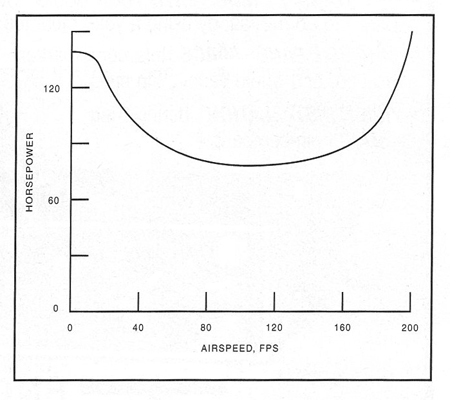
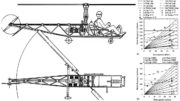
Figure 1. Using the outlined procedure, main rotor power required can be calculated for different airspeeds.
As the popularity of rotary wings grows in the custom aircraft community, understanding the basics of rotors becomes more important. The elements are discussed here with a minimum of confusing detail.
In forward flight, the helicopter rotor behaves about like a fixed wing of a span equal to the rotor diameter. It produces induced drag related to the disc loading, and profile drag that is characteristic of the blade airfoil in addition to the familiar parasite drag of fuselage and appendages.
The thrust produced by the rotor must include a horizontal component for propulsion, corresponding to the propeller or jet thrust of a fixed-wing aircraft, and a vertical component to balance gross weight.
Helicopter Basics
Vertical flight, hovering, and climbing or descending at zero airspeed differs from the airplane radically, since there is no horizontal airspeed to supply a flow of air to the lift system. The rotor must generate its own flow, just as a propeller in static conditions does. To deal with this, equations similar to those for propellers have been developed. These define coefficients:
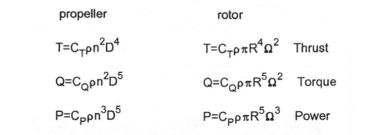
While these coefficients are not numerically equal, they express exactly the same relations. In the propeller equations n is in revolutions per second, and diameter D is used, but in rotor terms Q is rotation speed in radians per second, while radius R is used.
Air density is designated p = 0.002377 slugs per cubic foot at sea level in standard atmosphere. The coefficients incorporate the constants that accommodate the different definitions, but the physical relations are identical, as you can see by comparing the expressions.
Hovering The Helicopter
A rotor in hovering flight is the same as a propeller on a stationary airplane. The rotor and propeller must each induce a sufficient mass flow and accelerate it to produce thrust. If the propeller is on an airplane that is moving, or if the rotor is climbing, the increased mass flow reduces the acceleration necessary to generate the thrust, and the operation becomes more efficient.
Ground effect is about the same on helicopter rotors as on fixed wings—it reduces the drag and power required to maintain flight. Since hovering ceiling is crucial to helicopter operations, it is specified either in ground effect (IGE) or out of ground effect (OGE).
A basic difference between a helicopter in horizontal flight and an airplane is that the helicopter speed may not be limited by available power. The limit may be defined by stall on the retreating blade when increasing angle of attack due to cyclic pitch control or flapping exceeds the stall angle.
Normally, some region of stalled flow is accepted, but when it spreads enough to interfere with blade behavior or cause excessive vibration it blocks further increase of airspeed. In some helicopters the available mechanical motion range of controls can set the limit, since the space is often confined.
High tip speed on the advancing blade can also set the airspeed limit, causing excessive vibration. Up to the point where other considerations limit speed, the power/speed relations of helicopters and airplanes are essentially the same. Power absorbed by the tail rotor is analogous to power due to tail surface drag, but likely to be substantially greater.
Above the transition speed for the helicopter and minimum power speed for the airplane, power required increases with the third power of speed. Below that speed, power needed by the airplane increases down to the stall or minimum speed. Helicopters can slow down to zero, and that is where the most power is required in the low-speed range.
Helicopters generally have power installed somewhat greater than the requirement for hovering under standard conditions. For practical operating reasons, the power available must be adequate to permit hovering on a hot day at some altitude above sea level. The result is that most helicopters can hover at several thousand feet in standard air.
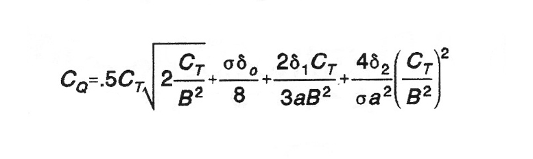
Years ago, the Army considered a hovering ceiling of 5000 feet on a 95°F day necessary to ensure useful performance under all probable conditions. Hovering power can be estimated by the following expression as given in Reference 1.
Where:
-
B is a tip loss factor.
-
a is blade section lift curve slope,
-
σ is rotor solidity (blade area/disc area).
-
δ is a polynomial term coefficient approximating profile drag of blade airfoil.
The first term is the induced power. The expression is for a rectangular blade with ideal twist (to provide a constant lift coefficient along the blade). It can be used to estimate performance of other blade planforms and twist with suitable adjustments.
In hovering flight the fuselage and hub drag are generally ignored, since the rotor induced velocity is relatively small at the disc loadings of typical helicopters. The tip loss factor B is a function of thrust coefficient and number of blades, usually between about 0.93 and 0.97 for typical rotors.
Forward Flight
Forward flight power requirement is more complex, and Reference 2 presents a method developed by NACA, based on summing four contributions to the power demand: rotor induced power, blade profile drag power, parasite drag power of fuselage, hub and tail rotor and climb power. For level flight, the fourth term is omitted.
NACA published charts for estimating performance, using Cp/CT ratios that are convenient to calculate. As shown in Reference 2, the induced power ratio can be approximated as Cpi/CT = CT√2m for low tip speeds and inflow velocity ratios; m is the tip speed ratio V/WR.
For parasite power ratios, it is simple to sum all the parasite drag contributions at any convenient speed, and calculate an equivalent drag area for a drag coefficient of l.0. Then the parasite power ratio is:
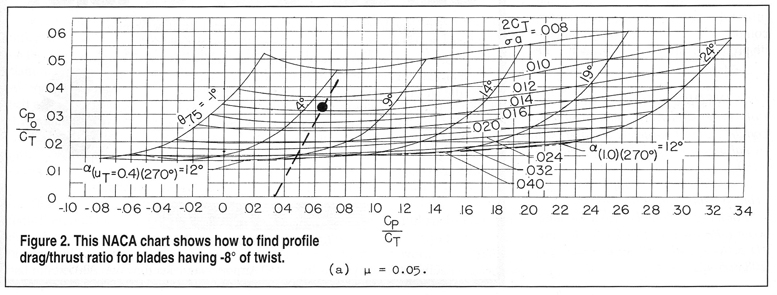
Use the NACA charts in Reference 2 (shown here in Figure 2) to compute the sum of the power ratios. Locate a point on the horizontal scale at the resulting value. From there, draw a line at a slope of 2:1 up and to the right. Opposite where this intersects the curve for 2CT√σa (interpolating between curves if necessary), read Cpo on the vertical scale at the left, and add this to the power ratio total.
This result is then applied in the equation above defining the power P in foot pounds per second. (Remember that CT can be found by solving for it in the thrust equation, approximating that thrust equals weight for level flight.) Dividing this power value by 550 then converts the result to horsepower.
Remember that the charts yield the profile power ratio; that’s why the equation for it was missing from the above procedure. Also, by choosing tip speed ratios in multiples of 0.05, the charts can be used without interpolating between them.
For values of tip speed ratio and rotor angle of attack a the simplifying assumptions applied here are sufficient for preliminary estimates. Additional parameters can be read from the charts and equations in Reference 2 for more detailed computations.
Figure 1. shows results for a 1400-pound helicopter with a 25-foot-diameter rotor; solidity, a = 0.10; lift curve slope, a = 5.73/radian; rotor speed, Q = 48 radians/second; and f = 1.5 sq. ft. The same procedure can be used to estimate the power absorbed by a tail rotor, which is part of the whole performance determination for an actual helicopter design.
Some terms were omitted here for clarity but would be included in any working calculations to include climb performance or rates of descent in autorotation. The presentation was designed to introduce the principles involved, without being overwhelmed by the details of actual design work.
REFERENCES
1. Alfred Gessow and Gary C. Mey ers, Jr. Aerodynamics of the Helicopter, Macmillan, 1952.
2. Alfred Gessow and Robert J. Tap-scott, NACA Technical Note 3323, Charts for Estimating Performance of High-Performaces Helicopters, Langley Aeronautical Laboratory, 1955.
Be the first to comment on "Helicopter Performance Basics"