
Henry L. Kelley
Retired Army Research Engineer
(NASA/La RC)
Currently Consultant for BLR
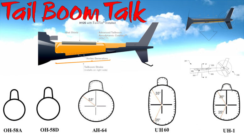
Introduction: Rotor wash passing over the enclosed tailboom of any single-rotor helicopter creates pressures along the sides of the tailboom. In hovering cross winds or during near-hover side ward flight, these flow conditions and pressures on the tailboom are created.
This phenomenon was noted in the early 1980’s in NASA studies. Engineers at Westland Helicopters reported on this phenomenon in 1985 concerning its Sea King noting that a single strake on the tailboom improved tail rotor effectiveness, improved yaw control and reduced pilot workload.
Army/NASA engineers studied this phenomenon intensively from about 1975 through 1993, measuring aerodynamic and flight control effects for a variety of strake configurations on a number of helicopter tailboom shapes in both wind tunnel and flight.
Strake configurations were tested, ranging from a single strake to three strakes with varying placement and strake heights. Through this research, data was developed that indicated the best aerodynamic configuration for all shapes tested was a dual strake configuration. (Note: editor emphasis added)
Tailboom strakes have been shown to produce significant improvements in stability, control effectiveness, and useful power (which improve higher altitude operations). The results are reduced pilot workload, reduced fuel consumption, increased payload, increased range, increased crosswind operating envelope, and therefore improved safety.
After extensive wind-tunnel model and flight-testing, a clearer understanding of the factors involved in dual tailboom strakes was developed and, in turn, patented by NASA.
The NASA patents were licensed to Boundary Layer Research-Aerospace, LLC. (Formerly BLR, Inc). The technology has been developed and refined by BLR for use on a number of currently operating helicopters and about 600 strake sets have been marketed worldwide.
Related Helicopter Aerodynamics
As late as the mid 1970’s, helicopter designers and researchers were having difficulty completely understanding how to size the tail rotor so that a new design had the proper amount of yaw control available. The major part of this lack of understanding was understanding all the ingredients that affected yaw control.
It was, of course, known that the tail rotor must be sized to handle the main rotor torque, weathercock stability (mostly caused by the tail rotor itself), any external disturbance such as winds and control of the helicopter itself, such as needed in maneuvering flight. The other ingredient was known to be the fuselage, but it wasn’t understood what part the tailboom played.
In an effort to gain more understanding into what these various components played in yaw control requirements, US Army researchers at NASA’s Langley Research Center built a powered helicopter model that could be tested in a building block fashion to see and understand how each piece affected the total yaw control picture.
From these tests, it was found that the aerodynamics of the tailboom was a significant player in the yaw control requirement, especially during hover and low-speed flight.
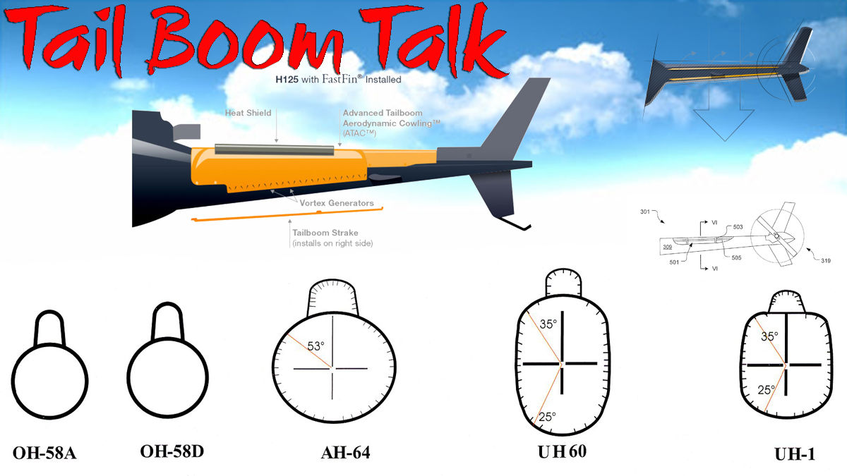
As a result of the larger-than-expected contribution of the tailboom aerodynamics, large-scale two-dimensional (2D) models were built and tested in order to gain a detailed understanding of their contribution. The primary shapes tested are shown in Figure 1.
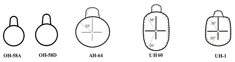
Figure 1: Some of the tailboom cross sections studied by the Army/NASA
The tick marks shown around the periphery of three of the tailboom shapes represent where pressure gauges were located. Each model also had a six-component strain gauge balance to measure forces and moments. Several other tests were performed in succeeding years, but will not be discussed here.
Aerodynamics of the Tailboom
The 2D testing of three shapes mentioned previously (UH-60, AH-64, and UH-1) concentrated on and simulated the hover and low-speed, cross wind flight conditions. In simulated cross winds in the wind tunnel, the tailbooms produced a side force that could be predicted to work against the tail rotor primarily in right sideward flight.
Of course, there was also a down load on the boom. As the angle of attack of the model was increased to simulate sideward flight, the side-force increased to a point where the tailboom stalled at the higher angles, indicating wing-like aerodynamic characteristics but with a low lift-to-drag ratio. The complete results of this early investigation are given in NASA TP-2506.
Introduction of the Strakes
Based on wind tunnel analyses of the tailboom force data and pressure data plus some calculations based upon these data, it was indicated that, if the unwanted tailboom side force could be eliminated or reduced, the extra pedal margin given back to the pilot could be beneficial in many ways, especially in performance and safety gains during hover and low-speed flight.
Since weathercock stability (or static-directional stability) of a single rotor helicopter is ample (due mainly to the tail rotor), taking away that portion contributed by the tailboom will not cause a problem.

Figure 2: Airflow over tailboom without strakes.
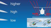
The angular location of the strakes on the tailboom models was determined by maximum suction pressure measured during the tests. The height of the strake was enough to: separate the flow and keep it separated past the bottom of the tailboom.
The height of the strake is of major importance because of the download loss considerations. The height of the strake should be such that the flow stays detached from the tailboom and does not reattach.
In flight tests, as a final check on the correct height of the strake used by BLR, the tailboom is tufted and flights are conducted to insure that the whole tailboom on the port side exhibits flow separation. On occasion, adjustments have to be made in height and angular placement to obtain better performance.
The length of the strake is generally the entire length of the tailboom unless prohibited by obstructions. It was noted during the analyses of the data that when the lower strake was used in conjunction with the upper strake, the benefits of the strake was extended over a wider range of angles of attack.
This indicated that more benefits could likely be gained in flight with the double-strake configuration. A sketch showing the airflow over a tailboom with strakes is shown in Figure 3.
Early Flight Investigation
A flight investigation was the next logical step in learning the effects of tailboom strakes on the overall flying qualities of the helicopter. Some results from a flight investigation will be given here although it wasn’t the first participated in by the NASA/Army-Langley Research Center.
The aircraft used Figure 3: Airflow over a tailboom with two strakes to determine the effectiveness of the tailboom strakes on yaw control during hover and low-speed, cross-wind flight was an instrumented Bell 204B.
Effects of the strakes in forward flight were anticipated to be of little or no value. This judgment was in part because no effects had been noted by Westland Helicopter on the earlier tests of a Royal Navy S-61 that uses a single strake.
Three configurations were investigated: (1) baseline (strake off), (2) single upper strake, and (3) double strake (upper strake with a lower strake on the same side of the tailboom). Cross wind data was obtained in five-knot increments of airspeed from 0-35 knots and in 30-degree increments of wind azimuth from 0 to 360-degree. (At critical azimuths, 15-degree increments were used).
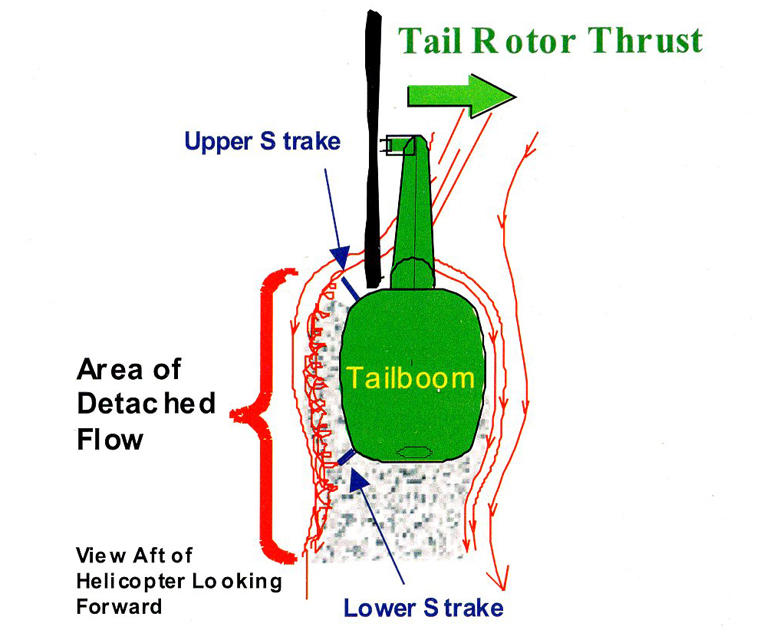
Figure 3: Airflow over a tailboom with two strakes.
At the most critical wind azimuth (60-degree off the right of the aircraft’s nose) and airspeed (20-knots) in terms of tail rotor power; the strakes improved the pedal margin by 6% of total travel and reduced tail rotor power required by 17%.
If the tail rotor is limiting the helicopter’s performance (that is, the engine or the transmission or drive system is not limiting) then this 6% extra margin in pedal could yield an additional 800 pounds of payload or 3000 feet of operational altitude for the Bell 204B.
These numbers are based on data in the pilot’s handbook and not on actual flight data with the strakes. Actual proof of the benefits must come from flight tests. One other benefit of the strakes noted by the pilots in low-speed flight was the improvement in precision controllability by about 50%.
The increase in steadiness of the aircraft with stakes is probably achieved because airflow separation is fixed on the tailboom so that random separation and reattachment of the airflow does not occur. Based on just a few flights between sea level and 2000 feet, the strakes did not appear to affect flying qualities between 35 and 100-knots. All of these results can be found in NASA TP 3278.
Experience at BLR-Aerospace
During the 1990’s NASA obtained three patents on the double strake configuration. BLR, located in Everett, Washington, began working with NASA on the strake and licensed the patents from NASA in 1999.
It was BLR’s intention to obtain FAA STCs on as many helicopters as economically feasible and whose numbers made sense from a marketing standpoint. The first STC obtained was on the UH-1H. Additional STCs have been obtained on other helicopters in the UH-1 and Bell 206 families.
Flight testing has been conducted by BLR on a commercial S-61, US Coast Guard H-65 Dauphin, US Army UH-60, and a Bell-412, just to name a few. Going from research to FAA certified strake hardware required many improvements and refinements.
For example, the strakes were built as light as possible, attachment techniques have been an ongoing refinement, and the development of test methods and hardware to insure that the strakes do not have a detrimental effect on the strength or the dynamics of the tailboom have been conducted.
During flight testing over the past nine years, BLR has documented other benefits of the strakes that were not detected during research at NASA. In most cases, the strakes are manufactured out of metal but they can also be built from composite material if required.
It has always been suspected that the benefits of the strakes would be the greatest during hot, high altitude and heavy gross weight conditions. If yaw control margins are small at sea level, then the margins decrease with altitude.
This fact was highlighted during a cooperative flight-test program with Bell Helicopter and BLR where an instrumented Bell-412 was tested at the Bell plant in Texas (2000 feet density altitude), Alamosa, Colorado (5500 feet), and Leadville, Colorado (12,000 feet).
While virtually no performance gains in terms of payload were noted at 2,000 feet, the results at Leadville were much more beneficial. It should be noted that an additional modification was made to the Bell-412 in the form of a small vertical fin cutout that was designed by BLR to yield added benefit for yaw control margin.
The fin cutout was called the “Fast-Fin”. The fin cutout reduces fin blockage and allows the tail rotor to operate more efficiently giving the pilot additional control margin. Based on initial measured results in hover from the Bell/ BLR/FAA test team, with the addition of the strakes in combination with the Fast-Fin, the -412 lifted an additional 1,300 pounds in ground effect and 600 pounds out of ground effect.
It was documented under the same hover conditions, that an extra 20-knots of hover cross wind capability was added at all wind azimuths. These results add to the body of evidence that you must test hot, high, and heavy to know where the strakes will do the most good. If, however, you are running out of pedal at sea level, the strakes can buy you that extra margin that you need.
To date, between 600 and 700 strake kits have been marketed worldwide including the US, Canada, Germany, New Zealand, Australia, Jordan, Columbia and Saudi Arabia. An on going program at BLR is continuing to obtain FAA certification on additional helicopters.
Concluding Remarks
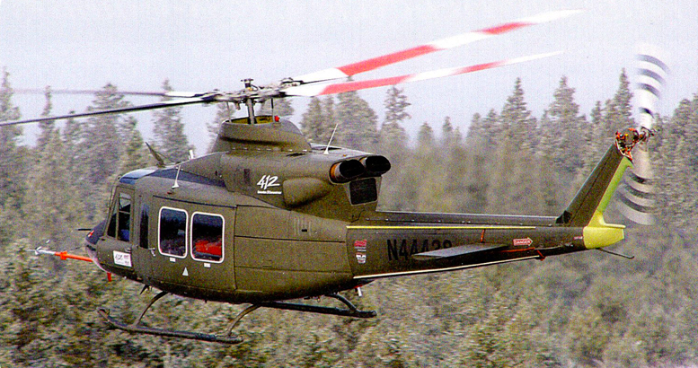
Figure 4: Bell-412 with dual strakes on the tailboom and Fast-Fin undergoing high altitude testing
Army/NASA engineers at the Langley Research Center studied the effects of helicopter tailboom aerodynamics on yaw controllability during hover and low-speed cross winds and it was found that the boom side forces created an adverse yawing moment that required additional yaw control during these critical crosswind conditions.
In order to give the pilot back this yaw margin, a double strake installation along the side of the tail boom was conceived and investigated and found to work quite successfully. Wind tunnel tests were made to provide design guideline information and data were obtained on several boom cross-sectional shapes.
Flight results confirmed the wind tunnel data results. NASA obtained patents on the double-strake configuration and in 1999 licensed them to Boundary Layer Research. BLR has obtained a number of STC’s on a range of helicopters and has marketed over 600 strake kits worldwide and continues its efforts on additional helicopter types.
Benefits of the strakes are the largest during hot, high, and heavy operating conditions. Also, if yaw control margin is the limiting factor on the operational envelope, strakes can be of significant benefit.
A joint flight program between Bell Helicopter and BLR on a Bell-412 highlighted the benefits of the strakes under hot, high, and heavy operating conditions during testing at Leadville, Colorado.
Be the first to comment on "Helicopter Tailboom Strakes"