
B. J. Schramm Rotorway Scorpion Helicopters
THE PAST DECADE has seen a marked increase in enthusiasm on the part of the layman to become more knowledgeable about the field of rotary-wing aircraft and the possibility of owning a personal-type, rotary-wing Rotorway Scorpion flying vehicle.
Thus far, the seven major helicopter companies have pretty much confined their efforts to the larger utility and commercial-type vehicles with a prime emphasis being placed on design of rotorcraft for military application.
Only in the last few years has the total number of commercial helicopters operated in the United States exceeded more than a mere few-hundred machines. There are many reasons why major companies have not pursued the personal VTOL vehicle.
The most obvious reasons are the difficulty of transferring enough education about the helicopter in a short enough period of time to create a mass market, and the unwillingness on the part of these companies to gamble the financial commitment necessary to produce profitable results over such a long-range endeavor.

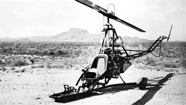
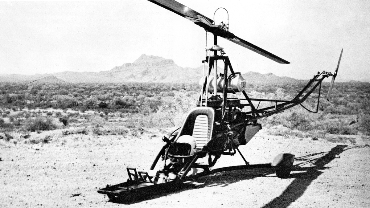
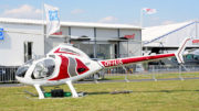
A truly distinctive and esthetic appearance makes the Scorpion stand out among the light rotary-wing craft.
Due to the vacuum created by the lack of suitable designs, many individuals and small companies have made untold attempts at successfully constructing a personal rotary-wing vehicle and capturing the homebuilt helicopter market.
Attempts by individuals have usually progressed to the point where enough hardware was tested to point out the magnitude of the problems which would be encountered if work were to be continued on the rotary-wing project.
The difficulty of designing, testing, and perfecting a full-service, vertical take-off rotary-wing vehicle can be outlined quite simply. A helicopter is essentially a series of vibrations all of which are being made to function in harmony with one another.
Three major flywheel effects are present:
-
the rotor-blade system,
-
the tail-rotor system and the
-
powerplant system.
All of these must operate in perfect harmony in order to achieve smooth flight. To top it off, it is the pilots job to manage 5 different controls to maintain that balance.
To understand the operation of any helicopter we must first understand the basic design of the different types of classical rotor-hub configurations, For our purposes here, these configurations may be categorized into the teetering or semi-rigid hub, the fully articulated hub, and the completely rigid hub.
The helicopter teetering, semi-rigid, or see-saw hub has its blades affixed rigidly in such a manner that no motion can exist between the hub and blades other than a rotational movement of the blades on a pitching axis (feathering).
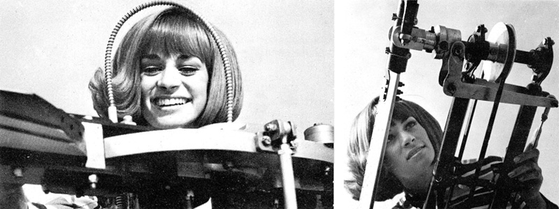
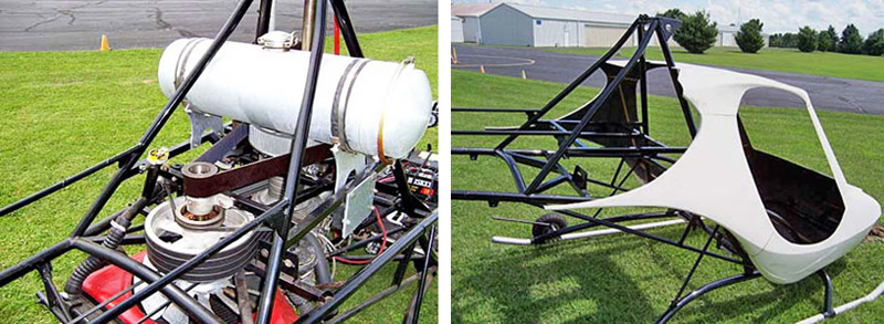
LEFT: An elliptical rotor-hub plate and circular, flexible push-pull cable are the identifying features of the Scorpion hub design.
RIGHT: Simplified tail-rotor design is apparent, where blade construction is a wraparound aluminum skin riveted to a steel spar.
The rotor hub is connected to the drive shaft by means of a universal having one axis pivoting on the shaft and one axis pivoting on the hub. In order to achieve flight control with this type of hub system, designers have used many different types of intermixing linkages. The helicopters semi-rigid hub is limited to two blades.
The universal-joint axis which connects the helicopters hub to the universal serves as the pivot axis which allows one blade to climb and one to dive, or vice versa, hence the teetering hub.
In the fully articulated hub we have a condition where each blade, whether three or more depending on the designers prerogative, may perform three different motions in relation to the hub:
first, pivoting on its pitch axis (feathering);
second, advancing or retreating (lead-lag);
third, vertical movement (flapping).
Control of the articulated hub seems to be the simplest of all as a linkage may be connected from the blade-pitch horn directly to the swash plate with no intermixing of control required. In the rigid hub, the rotor hub is rigidly affixed 90-degrees to the main rotor shaft.
Blades are attached to the hub in the same manner as in the teetering type. They have freedom of pitch change only (feathering). Control of this type of hub has presented great difficulty.
Solutions to the problem of control have been achieved with the use of a small gyro which is controlled by the pilot and, in turn, controls the rotor blades.
Since the rotor blades do not have freedom of vertical movement (flapping), extremely high stress loads are imparted to not only the blades themselves but to the rotor hub.
Only recently has a truly successful light helicopter rigid-rotor hub been perfected, and it has yet to prove itself in mass operation.
The choice of rotor-hub design for the Rotorway Scorpion was dictated by the type of market for which the craft was designed. Since the Scorpion is tailored for the novice sport flyer, it had to meet a far more rigorous set of safety Standards and at the same time be the most economical configuration possible.
Conventional helicopter controls include Standard cyclic and collective control with coordinated throttle, foot pedal directional control via a push-pull cable, and an over-center cam-locking clutch lever for rotor engagement.
There are many disadvantages inherent in all rotor-hub designs. One of the greatest is found in the fully articulated system. A condition known as ground resonance is very easily set up with this type of hub design – or vortex ring state in a two bladed design.
During take-off or landing, if the helicopter is permitted to linger in the condition where a very small portion of its weight remains on the ground or, if during a landing collective pitch is not reduced properly so as to place the craft firmly on the ground and thus avoiding the momentary minimum-weight condition, it is possible for the rotor-blade system to go out of phase.
Essentially, what happens is that one blade will dip beyond the tip-blade path of another, causing a serious oscillation which can disrupt the entire blade system to the point where self-destruction will occur.
For the novice pilot, therefore, the articulated system becomes difficult to learn to fly as it cannot be bounced around on the ground without the possibility of causing the occurrence of ground resonance.
A rigid-hub system has the basic disadvantage of encountering high stress loads in operation. Therefore, constant attention must be given to the dynamic components to determine that a safe usable lifetime exists. It also becomes susceptible to rotor mast bumping in negative G situations.
Exotic materials must be used in the rotor hub to withstand the very great forces which it encounters. The teetering semi-rigid hub has the disadvantage of having to intermix the cyclic and collective control in order to achieve proper vertical and directional control.
This design is most desirable however, due to the fact that it is difficult, if not impossible, to put into ground resonance regardless of the failure of the helicopter pilot to respond properly at the controls.
The choice of this type of system for the Scorpion dictates the necessity of a breakthrough in control design. In a semi-rigid hub, the collective control changes the blade pitch relative to the hub. Cyclic pitch or directional control is achieved by tilting the rotor hub with respect to the main drive shaft.
Prior control designs for the semi-rigid helicopter rotor hub have encountered difficulties in achieving Separation of the cyclic and directional control because of the fact that a mechanical linkage becomes a design problem when variables in more than one plane are introduced.
Mixing of cyclic and collective control for the semi-rigid hub has resulted in considerable mechanical complexity. In the Scorpion, however, these two controls are kept completely distinct by tilting the hub only with the cyclic control and using a flexible push-pull cable for separate collective control.
A proper collective pitch setting is maintained regardless of the position of the cyclic control. This patented system has thus far proven very successful and, at the same time, has greatly simplified mechanics in this area of vertical flight.
There is more to rotor-hub design than just control and design of the hub itself. Different hub designs require a corresponding difference in blade design. The complexity in the design of a helicopter rotor is due to the high, forces under which it must operate.
The significant forces acting upon a helicopter rotor blade are:
-
ROTORBLADE CENTRIFUGAL FORCE
In the Scorpion helicopter, for instance, due to the tip speed and weight of the blade, a centrifugal force of nearly 8000 lbs, or the equivalent weight of two Standard automobiles is placed on the end of the blade while in operation.
This amazing centrifugal load required that some means of transferring this tremendous stress from the blade to the rotor hub (at the blade root) be employed. The semi-rigid hub has its blade rigidly affixed with freedom of feathering only.
Therefore careful attention must be given to the blade-retention system on this particular type of hub. In the case of the Rotorway Scorpion, a series of fiberglass doublers is used.
-
ROTORBLADE TORSIONAL LOAD
Unlike the autogyro, a helicopter shaft has a considerable torque loading imposed on it in order to rotate a blade system under positive pitch. In the case of the Scorpion, approximately 600 ft. lbs. of torque is applied to the main shaft.
This high torque loading on a rotor system causes pitch instability on a rotor blade which does not have sufficient stiffness for its application.
-
ROTORBLADE CONTROL FORCES
When a movement of the cyclic control is made, a requirement is placed on each blade to respond precisely to the degree of control input. If each blade in the rotor system does not respond in an identical manner to its mate, an out-of-phase condition will occur resulting in severe cyclic stick feedback due to the out-of-track operating condition.
Helicopter blades must also be balanced properly chordwise in addition to being balanced very closely against one another. It is apparent that the many forces acting on a helicopter rotor blade require that a careful study be made in this area before initiating construction and testing.
A well-designed helicopter rotorblade must perform acceptably under all operating conditions and yet achieve a reasonable lifetime.
In the Rotorway Scorpion helicopter, three dissimilar materials have been chosen for blade construction which, when assembled, provide most adequately for extended operation under their normal operating load. This patented design is a D-section steel leading edge which is interlocked 10 a V-section aluminum trailing edge.
This assembly is bonded and screwed to a birch main spar which runs the length of the blade. Not only does the steel leading edge provide excellent anti-abrasion characteristics, but it also serves as an I-beam member greatly enhancing the stiffness ratio of this design.
Space here will not permit a complete discussion on all of the fail-safe features of the Rotorway Scorpion helicopter rotor-blade and hub-design concept; however, many significant features are employed making this a very redundant design. Power transmission in a helicopter tends to become a complex task.
A method of transferring power from the helicopters engine to the main rotor and from the main rotor to the tail rotor must be able to transmit capably the load requirement, and at the same time torsional vibration from the engine must be limited as much as possible.
Weight of the helicopters drive train must be watched carefully so that performance of the craft is not impaired. A mechanical right angle gear box and shaft drive are most commonly used in utility and commercial helicopter designs.
Unfortunately, again due to the extremely high torque loading (because of high speed-reduction ratios), this type of power transmission system becomes prohibitively expensive when scaled down for an ultra-light design.
In order to provide for the greatest ease of maintenance and lowest initial cost, the Rotorway Scorpion helicopters drive-train design uses off-the-shelf components, avoiding specialized gearboxes that require advanced maintenance proceedures.
Even though significant savings are achieved, no loss of safety or reliability is incurred in the drive system. Six V belts transfer the power from the engine to a countershaft containing an overrunning clutch for autorotational or power-off operation.
The second stage of this two-stage engine-to-rotor reduction uses an industrial rated dual row chain in an oil bath. A high torque (due to the reduction) and lower speed situation is encountered in the second stage and a chain serves most capably in this function.
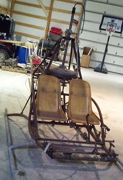
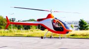
Rotorway helicopter airframe of two seat Scorpion using the same drive layout design as the Scorpion single seat (beefed-up).
The higher speed, lower-torque first-stage reduction uses the belt concept which works ideally under these conditions. Homebuilt helicopter designers have experimented with a number of different tail-rotor drive configurations.
Due to the extended length of the tail boom on a single-rotor helicopter, there are a number of disadvantages in using a shaft drive on an ultra-light VTOL. This is especially true in the Scorpion, as a somewhat flexible tail boom is used to reduce cyclic and directional-control cross couple.
The Scorpion kit helicopter uses a multi-stage v-belt drive to the tail rotor. This design has a number of inherent safety features. Belts are not subject to torsional fatigue as is a long drive shaft. Tail-rotor drive gear box overheating is eliminated. The reduced maintenance requirements are obvious.
Since the normal helicopter tail rotor requires approximately ten percent of the engine’s power for operation (much less under cruise condition), the belt design is ideal for the Scorpion helicopter application.
The tail rotor which is necessary in a single-rotor system helicopter has long been a target of discussion among rotary wing designers. Since it is definitely a power-robbing system, many efforts have been made to eliminate it totally – see “NOTAR, tandem and coaxial” designs.
The function of the tail rotor in the helicopter is primarily to counteract the torque of the main rotor shaft. Therefore, if we eliminate the tail rotor other means must be provided for balancing or counteracting shaft torque.
The most common and successful means of doing this has been the use of two separate rotor systems in tandem. Unfortunately, not only do we add a tremendous amount of complexity to our drive train, but we double the number of blades used, in addition to another rotor hub.
At the same time, we encounter a complicated control-system design problem. Directional control becomes complex because of the close and opposed coordination required in the two rotor systems.
Another method of eliminating the tail rotor has been to place two rotor systems on the same shaft and rotate them oppositely – effectively cancelling out equally the torque of each blade against the other.
Here again, not only do we encounter an additional hub and blade system, but the cancellation of our stabilizing gyro which aids us tremendously in directional control when a rotor system operates singly.
In a hover, a counter-rotating or coaxial helicopter system can be easily tilted beyond its degree of controllability by the novice pilot, reducing pilot load and control management.
The use of the single main rotor and tail-rotor design of the Rotorway Scorpion helicopter was carefully premeditated and the simplicity of this entire craft has been greatly enhanced by adhering to this more conventional type of design.
The Scorpion helicopter tail rotor amounts to a very simplified mechanism. A straightforward design is used which consists of a thrust washer-retention system, and simple wrap-around aluminum-skin rotor-blade construction.
This tail rotor blades are teetered at 90-degrees, greatly reducing operating stress loads. Pitch control is achieved by a simple push-pull cable. Due to the power available in the class of powerplant used, the tail-rotor horsepower loss does not significantly affect Performance of this aircraft.
It can be readily seen that the addition of another complex rotor system would be foolhardy for the small amount of efficiency gained by eliminating the tail rotor design.
An aircraft, either fixed wing or rotary wing, should be designed in and of itself for whatever particular performance characteristics the designer requires.
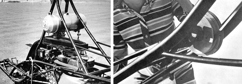
LEFT: Replacing the heavy and dirty secondary chain drive with a cog belt is a popular customer modification.
RIGHT: Simple yet sleek fiberglass outer cabin improved the duck-bill design.
Unfortunately, since the time of the Wright brothers, few aircraft designers have found themselves in a position to pick and choose regarding the type of powerplant dictated by their design.
An aircraft, especially a VTOL, must be designed with an idea of powerplant availability in mind. Aircraft engines with a power-to-weight ratio of one horsepower per pound are not to be found in abundance.
The only category of powerplant which can meet this specification to date is the turbine, and turbines are certainly not for the average sport aviation enthusiast. A horsepower-to-weight ratio of one to one is almost a must for the ultra-light helicopter category.
Many commercial helicopter engine designs in the low-horsepower range are available which are capable of producing this kind of horsepower; unfortunately few of them can boast any reasonable lifetime when operated continuously at their maximum horsepower output.
For 20 years now, a formerly cranky unsophisticated putt-putt known as the outboard motor has been quietly developing its potential at producing usable horsepower at relatively low weight. Presently, the outboard motor is in truth the poor man’s gas turbine.
This category of engine is not only mass-produced to a high standard of excellence, but is capable of extended operation at firewall level. Outboard powerplants have gained in horsepower year after year to the point where their application in light aircraft and VTOL usage is ideal.
Initially we might question the use of water as a cooling medium. We must consider that in a helicopter in a hovering condition we require what amounts to a stationary powerplant.
No ram air is available from forward flight and the engine is working its hardest in this flight condition. In this stationary condition, we find that water is a more efficient cooling medium than air.
Less power loss is encountered for the simple reason that we may move a smaller amount of air at a slower rate over a heat exchanger to cool the engine than we would in an air-cooled version – (forced air cooled).
The Rotorway Scorpion helicopter uses an outboard powerplant for these reasons. Adaptability, packaging, and ease of maintenance are additional factors in favor of this choice of power.
The safety of any VTOL design may be judged by two basic factors — the amount of testing to which the dynamic components of the craft have been successfully subjected, and from a pilot-forgiveness standpoint, the autorotation or power-off operating characteristics of the rotorcraft.
Extremely high stress loads are encountered in rotor-blade, hub, and control systems, and also in the extremely high-torque, high-reduction power-transmission drive system.
Design-safety factors for these systems must be in excess of normal safety factors and exhaustive test studies utilizing strain gauges strategically placed must be conducted to determine lifetime reliability. It is just not enough to be content with dismissing the problem of safety with: “I think it will hold.”
Any helicopter must have built into its mechanism the capability of immediate and automatically declutching of the engine from the rotor system should power failure occur or should the pilot reduce engine rpm to an idle in flight.
Any true helicopter is capable of landing safely without power as long as sufficient altitude and/or forward speed is maintained. Autorotation landings may be difficult for the novice pilot to master if the helicopter descends too rapidly in autorotation.
The only way to provide for an easier autorotation landing is to lower the disc loading (rotor-disc area divided by weight of the ship) of the helicopter and slow its descent rate. In addition, a lower disc loading will allow a wider margin for final contro-correction movements just prior to landing.
The Rotorway Scorpion helicopter has a two-pounds per square foot disc loading as compared to the higher disc loadings of three to five pounds for larger commercial VTOL’s. This light disc loading not only makes the Scorpion more docile in autorotation, but measurably contributes to the pilot’s peace of mind in flight.
The helicopter has the dubious reputation of being a difficult machine to learn to fly. The difficulty is not so much in the pilot mastery of the controls as; it is in being able to come up with the hourly rental cost. Solo time in a helicopter can be just as minimal as solo time in a fixed-wing aircraft.
A helicopter requires a little different type of coordination for flying than a fixed-wing aircraft; however, it is no more difficult to learn and, once learned, the technique can be improved.
Just as a fixed-wing pilot can learn aerobatics, a helicopter pilot can improve his proficiency in ground-taxiing maneuvers and in-flight maneuvers as he gains more supervised experience.
Since the helicopter is capable of landing and taking off in a spot just large enough to swing its rotor blades, a pilot really gets a sense of third-dimension maneuverability. The birdlike ability to be able to set down in any spot gives a true sensation of the freedom of flight.
The helicopter is truly a sport flying machine because the fun of being able to make the ship an extension of one’s thought is both a challenging and rewarding experience. A pilot can practice and refine maneuvers of his own choosing, creating his own style as he progresses.
As the pilot’s responses become more adept, the ship will respond in a more agile manner. One need not be an experienced helicopter pilot to thoroughly enjoy flying a helicopter — questioning any helicopter pilot will bear this out.
Past Single-seat helicopter designs have been somewhat difficult to fly, and it was nearly impossible for the novice pilot to learn to fly them due to instability, partially because of their extremely light weight or design imbalances.
In the Rotorway Scorpion helicopter, however, many features have been added to make this ship control in the same manner and with the same degree of stability that is found in larger commercial designs.
These design features include the elimination of control couple between the foot pedals and cyclic control by means of a flexible ladder-type tail boom construction.
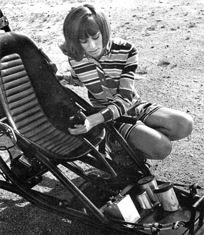
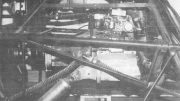
LEFT: AIl mechanisms and components are tucked away inside the slim-line fuselage constructed of 4130 steel tubing.
RIGHT: Tail-rotor drive is by means of three V belts running from the secondary drive shaft via two idler pulleys to the tail rotor.
The incorporation of a teetering-type rotor which, even though the Scorpion’s gross weight is only 750 lbs. maximum, allows this ship to fly with much the same degree of stability as the larger see-saw-type hub commercial designs.
Complete separation of the collective and cyclic control mechanism also adds to the degree of stability in control. Placement of the tail rotor outside of the rotor-blade disc area is a great advantage in regard to directional stability.
Due to the large diameter of the tail rotor, it also has an extremely low disc loading in comparison to larger commercial designs and therefore is considerably less sensitive than would be expected. Use of a high inertia blade design provides additional pilot forgiveness, especially in autorotation.
At best, the freedom of flight in a helicopter is difficult to describe and can only be truly appreciated by experiencing this exhilarating sensation for yourself.
To build a personal helicopter with your own hands and then experience the excitement of flight in the craft is a rewarding experience which few other projects can compete with.
The Rotorway Scorpion helicopter design was conceived for the sole purpose of adaptability to sport flying. The continuing goal of Rotorway has been to find ways and means of putting together a program in which this design may be shared with all those who desire to participate.
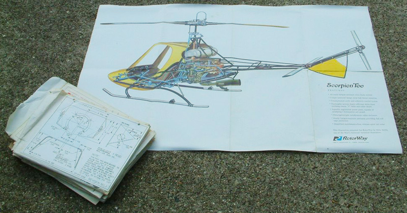
First release Rotorway Scorpion two seat kit helicopter assembly plans.
Be the first to comment on "The Birth Of Rotorway Scorpion Helicopters"