
Electronic Rotorblade Balancing
ARTICLE DATE: July 2008
I know the first time I saw an electronic blade balancer in action it appeared some magic was being demonstrated. The balancer equipment was mounted on the helicopter using some mystic rules, the helicopter spun up and the readings of IPS and Phase Angle were plotted on a piece of paper called the Polar Chart – a chart having a bunch of concentric circles with radial lines emanating out from the center.
It looked more like a gun target.
The IPS readings were laid out as a distance from the center of the chart and the Phase Angle determined onto which radial line the IPS were plotted. Then weights were added to the blades at some location mystically called out by the Polar Chart and interpreted by the magically endowed guy doing the balancing. I carefully observed this person and noted the usual number of fingers, hands, feet and eyes.
I could not find any real difference between him and me, so decided I should be able to figure out just what this magic was. I shall endeavor to explain my understanding of the magic of the balancer by first using a simple disc and mounting tube assembly, then a more representative rotor.
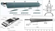
Fig 1 shows a disc connected to a flexible shaft with the disk & shaft rotating as a constant speed. A piece of reflective tape is put onto the edge of the rotating disc. A photo cell is mounted on a non-rotating part so that the photo cell sees the reflective tape as it rotates by.
The velocimeter is pointed directly at the shaft and is also mounted on a non-rotating portion located in line with, but below the photo cell, – If the disc is perfectly balanced, the IPS reading is 0, or very small, and the Phase Angle data changes in a noise like manner.
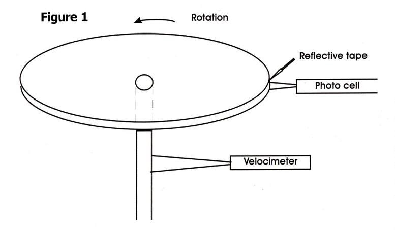
Definition 1: IPS is inches per second and is a measurement provided by the velocimeter of the amount of deflection of the shaft in response to a weight, causing the out of balance condition. The velocimeter has a narrow field of view so its measurement is enhanced when the velocimeter is pointed directly at the shaft.
Definition 2: Phase Angle is the angular displacement of the disc from the point when the reflective tape was in front of the photo cell to the point where the offending out-of-balance weight lines up with the velocimeter, which is where the strongest IPS reading is produced. The photo cell produces a pulse each time the reflective tape is in front of the cell.
For a complete rotation of the disc there is a pulse generated at 0° and again at 360°. If you have an event that occurs half way between the two pulses in time, this corresponds to an event with a Phase Angle of 180°. If the event occurs % of the way from the first pulse the event occurred with a Phase Angle of 90°.
Also by knowing the frequency of the pulses the rpm can be computed. E.G 10 pulses/sec would produce 600 pulses/min and, since you get a pulse for each complete revolution, 600 pulses/min would correspond to 600rpm.
Now let’s purposely introduce an out-of-balance condition by stopping the disc and inserting a small screw (see fig 2) into the disc some distance out from the disc’s center. In this case I’ll locate the screw on a line from the disc center to the reflective tape. When the spinning is resumed, the flexible shaft wobbles and vibration is felt.
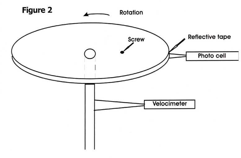
The shaft deflects in the direction of the added weight of the screw. This isn’t always true, but since this is my disc and my screw, this time it does. The balancer now shows a non-zero IPS reading brought on by the screw weight. Since the screw is on a straight line out from the disc’s center to the reflective tape and we are assuming that the velocimeter is mounted adjacent to the photo cell, when the velocimeter peak reading occurs, the Phase Angle data reads 0°.
This tells us that the offending out-of-balance weight is on the line from the center out to the reflective tape. We knew that. If all we had was the single IPS reading, we would know we had an out of balance condition but would not have enough data to determine the location of the offending weight or how to correct the situation.
An oversimplification of the velocimeter operation is described by saying that with the velocimeter mounted on a non rotating location, pointing directly at the rotating shaft, the velocimeter reading is the strongest when the out-of-balance weight (in this case the screw) comes around to the position directly on a line through the velocimeter and the center of the rotation. (Technically this is not absolutely correct, but for all practical purposes it can be used).
The velocimeter can be mounted anywhere around the shaft; as long as it is pointed directly at the shaft it will get the same IPS reading. By knowing how long, in time, after the photo cell pulse that the velocimeter reading was taken, an estimate is obtained indicating the disc position when the velocimeter read its highest reading. In our example, the screw was put into a position that was going to cause the Phase Angle measurement to be 0°.
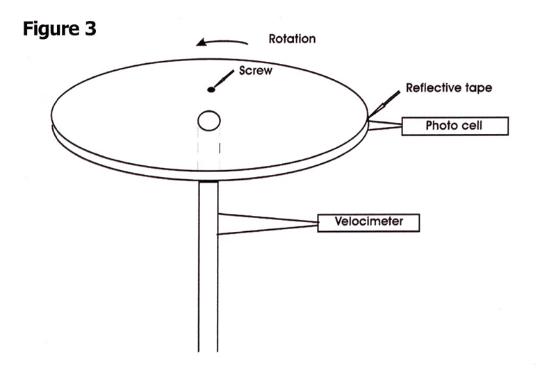
If I now move the screw to a new position, in this case 90° around the disc in the direction of rotation (see Fig. 3) at the same distance from the center. Now when the disc is spun up, the balancer will again read speed in rpm and will read the same IPS, but the disc and the reflective tape, will have to rotate 270° before the screw is again lined up with the velocimeter so the Phase Angle data is therefore 270°.
Also in our example, the velocimeter and the photo cell were mounted at the same angular location. This is not necessary. If the velocimeter was mounted 90° around to the left and the screw was installed on the line from the center to the reflective tape, the IPS reading would be the same but the Phase Angle data would be 90°. Because the disc would have to now rotate 90° to line the screw up with the velocimeter.
Now let’s assume that we have the first case, as in Fig. 1, only now it has a screw installed on the line from the center to the reflective tape as in Fig. 2. Assume also that the velocimeter is mounted below the photo cell also looking directly at the shaft. Let’s further assume that we don’t know where the screw is.
Murphy (sorry John) has installed the screw when we weren’t looking. When we spin up the disc and get a reading of IPS, say 0.4, the Phase Angle will say 0° or something very close to that. If we stop the disc and position it to the 0°, the reflective tape is in front of the photo cell, and we have the position of the maximum velocimeter reading.
Fig. 2. If we want to correct the out of balance condition, we would merely add some weight to the disc on a line extending from the reflective tape thru the center of the disc to the side opposite the shaft. This is to say we are going to “Add Opposite”. If we repeat the test but have not added enough weight we would get a reduced reading such as IPS = 0.2, Phase Angle still 0°.
If we added too much weight we could get a reading such as IPS = 0.3 and Phase Angle 180°. If we accidentally added exactly 2 times the weight needed, (and accidentally added it to a position exactly the same distance from the disc center as the Murphy weight) we would get a reading of 0.4IPS @ 180° The sudden switch of the phase angle by 180° indicates we have added too much weight and should reduce the weight and try again.
It is not necessary to have the velocimeter mounted directly beneath the photo cell. Successful balancing can occur if you have the photo cell mounted looking directly up and the reflective tape mounted on the blade. The velocimeter should be mounted pointed at the shaft.
When you get your reading of IPS and Phase Angle, merely turn the rotor system until you have moved the blades and the reflective tape, the angle amount as referenced to the photo cell. Now look over the velocimeter toward the shaft. Select a trial weight and add it on the side opposite the shaft from the velocimeter.
Yeah I hear you: On the blades, there might not be any place to put a weight just opposite the shaft. What do you do now?
In Fig. 4 shown below, there is a rotor blade with M for Master on the outboard end of one blade and S for Slave on the other, ‘RT’ refers to the reflective tape and ‘S’ is both the photo sensor and the velocimeter. For the purposes of discussion I have assumed that both photo cell and velocimeter are mounted near each other pointed toward the main rotor shaft.
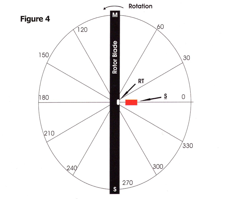
Another assumption is that the reflective tape was mounted on the swash plate or a portion of the rotor system rotating with the blades. Note this location of photo cell and velocimeter will yield a 0° or 180° phase angle for a simple chord-wise out-of-balance and a 90° or 270° phase angle for a span-wise out-of-balance.
Now if it is assumed that the blade shown is in perfect balance, when the helicopter rotor is spun up to flight speed and the helicopter carefully hovered, the balancer should just show IPS = 0 or and the Phase Angle should just jump around with noise-like readings.
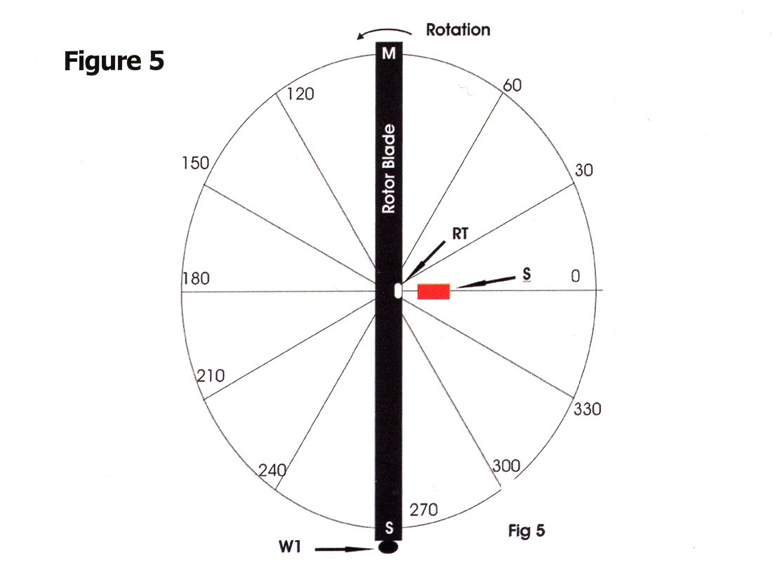
Now let’s suppose, that Murphy (sorry John) adds an out- of-balance weight out at the tip of the Slave blade; shown as W1 Fig. 5. Upon spin up and hover the perfect balancer will now show some IPS reading and the Phase Angle to be 90°. This is because the rotor must turn 90° in order that the weight W1 lines up with the velocimeter, where it must be to get the max velocimeter reading.
When the blade is positioned to the 90° location, as shown in Fig. 6, and if the out of balance weight that Murphy added could be seen, it would appear on the outboard tip of the S blade and would be on a line out from the shaft center directly over the photo sensor and on line with the velocimeter.
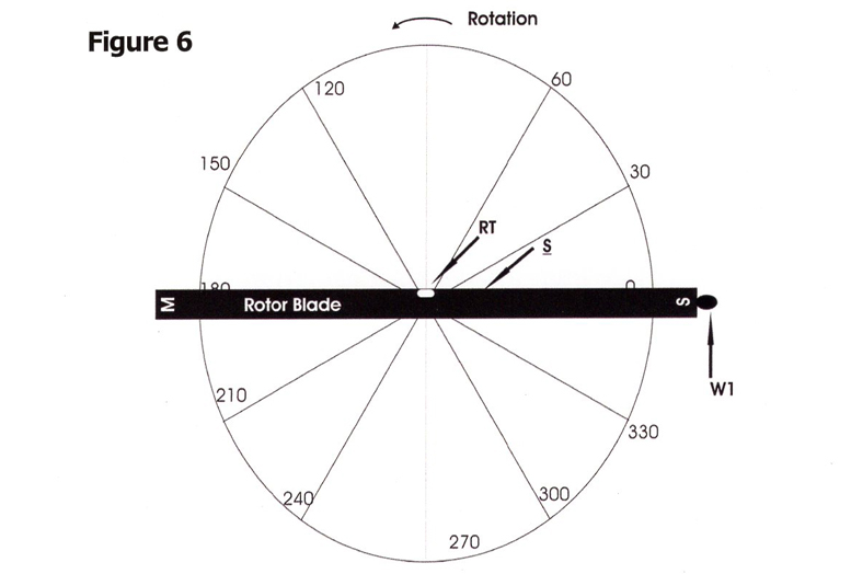
My corrective action is to add some weight to the tip of the master blade on the other side of the shaft from the velocimeter. This is again “Add Opposite” for adding weight to the opposite side of the shaft.
Now Murphy (sorry again John) is never nice enough to just add a single weight in an easy to find position. Let’s now assume that the devious Irishman added two weights: One on the tip of the Slave blade, W1, creating a span wise imbalance, and another W2 on the side of the rotor head, this one representing a chord-wise imbalance. See Fig. 7 below. Now you have the typical case when balancing a two bladed helicopter rotor.
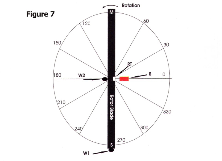
The Phase Angle will read somewhere between these two, which is caused by the velocimeter seeing an out of balance weight resulting from a combination of the two weights.
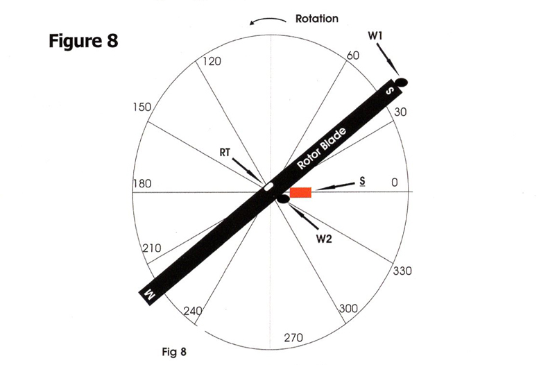
It is still possible to use the “Add Opposite” technique.
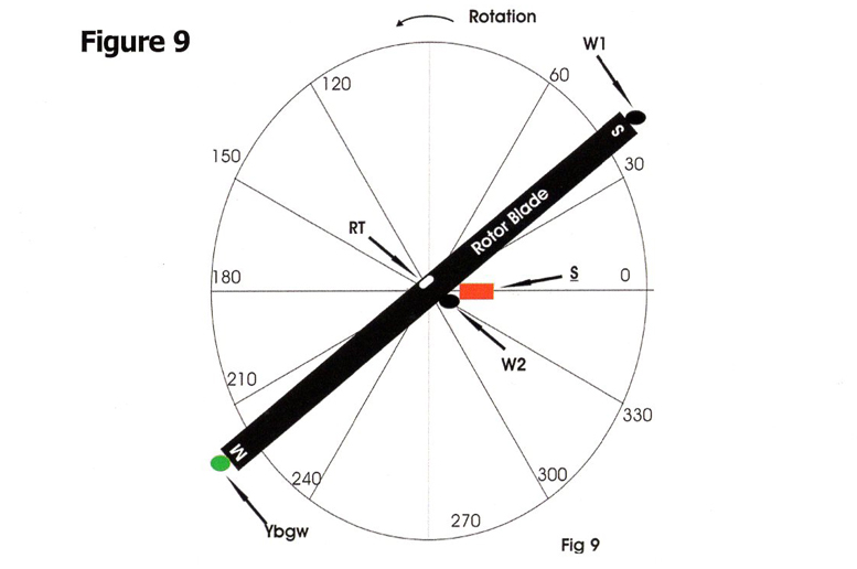
Align the blade to the angle measured from the photo cell and reflective tape, (see Fig. 8). Then sight over the velocimeter and add a weight YBGW (Your Best Guess Weight). There is no handy place to put the weight but just add it to the tip of the Master blade, (see Fig. 9).
If you can’t add some small weight to the tip, add several washers to a blade retention bolt on the Master blade because you want to “Add Opposite” as best as you can and the Master blade is the closest to being “Opposite”.
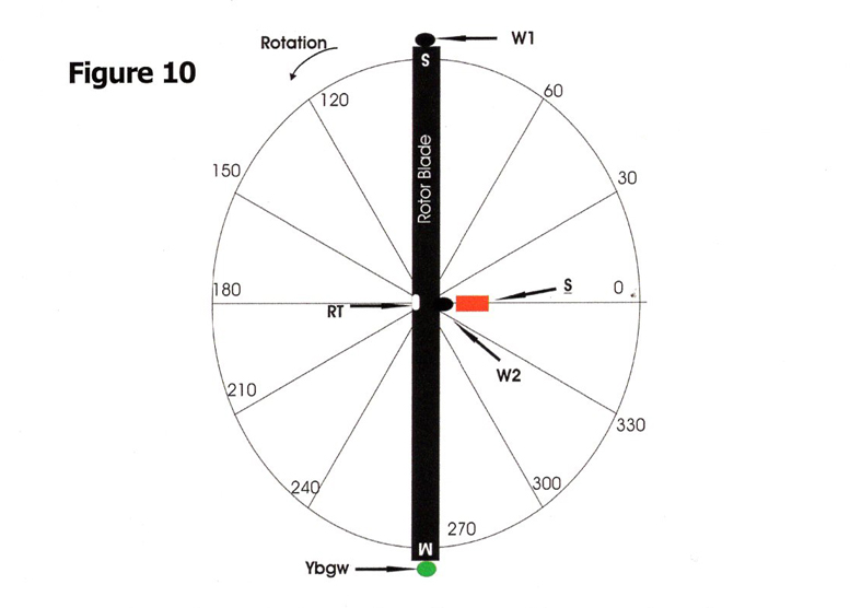
If you don’t add too much weight, a reduction in the IPS should occur with a corresponding increase in Phase Angle reading. If you were fortunate that the added YBGW was exactly what was required to balance the span-wise-out-of-balance weight ‘W1’, then the Phase Angle reading will be 180°.
Positioning the rotor to this phase angle (see Fig. 10) shows that the remaining out-of-balance weight is located chord-wise. The corrective action taken by most helicopter people, to correct a chord wise out-of-balance weight, is to lag a blade in order to move the center of mass of the blade system until it resides directly over the center of rotation.
I prefer to “Add Opposite” – adding a weight to the side of the rotor head opposite the velocimeter. This assumes that both blades have zero lead/lag, and whatever head shift is available is centered.
A word of caution: For first time balance operations, always start out at a low rpm and check for grossly out of balance conditions. This includes the tail rotor as well. Precision in statically balancing rotors prior to installation makes the job easier.
A passing note: “Add Opposite” does not work on the Safari tail rotor. “Add Same” is required. This is because the Safari tail rotor operates above its critical speed as discussed in a previous issue.
Note: These techniques have proven useful with both a Spurting balancer and a DSS micro balancer on a Safari helicopter. I have no experience with other helicopters or other balancers.
Why do most of the balancers used in rotor balancing refer to the vibration amplitude in IPS? A recent review of an old Reliance Technical Training Department text has a good description of the various techniques used to measure vibration amplitudes.
The three types discussed are;
-
Acceleration, data produced from accelerometers,
-
Velocimeters most normally encountered yield data in IPS, and finally
-
Position, which is data as gathered by one of our subscribers balancing his tail rotor – he used a dial indicator to measure the deflection caused by the out-of-balance in his tail rotor.
Why do the balancers tend to use Velocimeters which produce the IPS data?
Displacement: A machine that produces a .001″ wobble at 1000 rpm would be considered good and should last a long time. However if that machine had a .001 wobble at 10,000 rpm it would be considered to be in serious trouble. So displacement as a measurement of vibration amplitude needs some additional judgment and knowledge of the speed.
Velocity: Knowledge of the velocity of the vibration leads directly to an understanding of the energy involved in the vibration. KE = Kinetic energy = V2 MV-V = velocity. The goal is to minimize the IPS readings. We are in effect decreasing the vibration energy.
Acceleration: The accelerometers tend to be useful for higher speed machines. An example pointed out in the Reliance Training text was for a machine operating at 300 rpm, a vibration induced displacement of 0.8 inches would be required to produce one unit of acceleration and would obviously be noted. However for a machine operating at the high speeds of turbine engines, readings as high as 40 units of acceleration have been noted with no bad effects.
It has been demonstrated that if 1 IPS is bad at 1000 rpm, it is equally bad at 10,000 since the kinetic energy is the same in both rotational rates. This reduces the amount of judgment and thinking required to balance rotating machines. Velocity measurements alone give an indication of the health of the machine where both displacement and acceleration measurers depend also on knowledge of the machine in terms of both the direct vibration amplitude and the speed at which the measurements were taken.
So the balancer manufacturers have a good reason for using velocimeters. It makes life easier. I hope the above is useful.
Be the first to comment on "Using an Electronic Blade Balancer"