

Helicopter Rotor Typesy
ARTICLE DATE: October 2000
I’m very interested in simplifying the mechanics of helicopter design and their safety factors. Most specifically, the coaxial helicopter designs and their simplistic nature. I’ve done a lot of historical research on autogyro and helicopter design concept development, and have thus concluded that the coaxial design has some most favorable attributes.
The Sikorsky “XH-59A” or “S-69” coaxial helicopter design of 1978 is a design in point. It was once thought to be the fastest (compound) helicopter ever built, capable of 322 MPH, using a 36 foot rigid (ABC) advanced blade concept rotor system. There were problems with the twin vertical/rudders and horizontal/elevator size and design that could have been remedied.
Combining the Westland Helicopter of the U.K. “swept back blade tip design” with the Sikorsky S-69 overall coaxial design would make for a great non-conventional helicopter! Stan Hiller was on the right tract back in his “XH-44” and “UH-4” coaxial helicopter design rigid rotor system 1940’s days!
I admire Mr. Hiller greatly, for he did not follow the “calf-path” design methodology. He explored all rotor system design concepts for himself. The Sikorsky S-69 rigid-rotor design is proof of Hiller’s success.
The Russian Kamov Coaxial Helicopter models are the only present coaxial helicopters in world existence. I can make an analogy, I think of the Kamov to the Russian AK-47 rifle (much in demand by all our U.S. Special Forces: Army, Navy Seals & Air Force Commandos). They’re both design built for reliability, rigidity and overall, less maintenance!
I’ve started an archive of every coaxial helicopter design ever built through the flying prototype, and have designed an experimental, coaxial helicopter of my own. Compound helicopters were designed and developed to increase helicopter forward speed.
They pay for the higher speed in a decrease in vertical take-off and hovering capability, since the wing interferes with the airflow through the rotor; then, too, the added weight of its structure reduces the payload capabilities. The tilt-prop designs were another step forward on the increase speed scale; the large models were capable of 300 to 400 mph.
This system proved inferior to both the helicopter and compound helicopter in vertical take-off and in hovering ability; their propellers were not an efficient rotor systems. Control in hovering flight was not as good and, payload that could be lifted vertically was much less (for the same power) than with a helicopter.
Also, the vertical take-off of the tilt-prop designs were more of a strain on the engines than that of a helicopter. VTOL aircraft are not as safe as helicopters due to not having autorotational capabilities in an engine failure, these aircraft are completely dependent on their engines for vertical and horizontal vented thrust.
Advantages of coaxial over conventional helicopter designs:
-
Excellent maneuverability.
-
Good ground clearance.
-
Better lifting capability per main rotor diameters than single rotor configurations (approximately 1.75% greater increase per given rotor diameter).
-
As vertical separation of the coaxial rotors increases to about 17.5% of one rotor radius, they approach the power efficiency of an isolated single rotor configuration in forward flight. At 10% or less of the rotor radius vertical rotor separation, a 1.41% increase in induced power is required. As rotor separation approaches or reaches 25% of rotor radius, the harder the lower rotor has to work to develop and maintain its share of rotor thrust. “Vertical separation of rotor wakes determine efficiency.”
-
Coaxial configuration helicopters also avoid the tendency of the single rotor helicopter to roll during high speed flight. A rotor’s advancing blades combine their rotational speed with the helicopter’s forward airspeed to produce increased lift on one side of the rotor; the retreating blade, in contrast, subtract their rotational speed from the helicopter’s forward airspeed and produce less lift. The resulting asymetrical lift at high speed produces roll forces that increase with forward airspeed. Coaxial helicopters, whose rotors turn simultaneously in opposite directions, in contrast, present an equal number of advancing and retreating blades on each side, thereby neatly avoiding this problem.
-
Coaxial helicopters utilize all their power to generate lift and directional or forward thrust, instead of 15 – 20% power loss due to power required for anti-torque tail rotors.
-
Coaxial helicopters require less maintenance and weigh less due to having a shorter tail section, no tail rotor: drive system, no gearbox, collective or its control system;
-
Coaxials are easier to control in high crosswind or tail wind conditions due to their balanced main rotor torque and shorter tail sections. Conventional helicopters, due to their long tail sections, tend to wind vane and can run out of positive tail rotor pedal for anti torque yaw control;
-
Coaxials are safer, there’s no chance of yaw or directional control loss due to tail rotor failure or possible tail rotor mishaps;
-
Coaxial helicopter are a more compact design due to the smaller length tail sections based on the radius of smaller diameter rotor disc requirements; and
-
Coaxial designs also offer a greater center of gravity payload range.
Note: Past coaxial helicopter designs, especially of the 40’s lacked development of vertical/rudder tail fins for aid to differential collective for lateral (OGE & IGE) yaw control and a horizontal/elevator for aid to cyclic pitch control at cruise speeds, in place of differential collective, the use of a braking system to engage either one or the other of the concentric rotor shafts to offset rotor torque for yaw central needs further design exploring. Both aided systems for yaw and pitch control, I employ in my coaxial helicopter design.
Doing It Vertically
ARTICLE DATE: June 1991
Are homebuilders ready for V/STOL aircraft?
By Philip Terpstra
High-speed vertical takeoff and landing aircraft have long been desired. Conventional air planes have a great limitation because they require a ground run at the beginning and end of every successful flight.
Point-to-point transportation is more desirable than airport-to-airport travel. High-performance airplanes also have rather high minimum flight speeds, with proportionately higher risks during takeoff, landing and training.
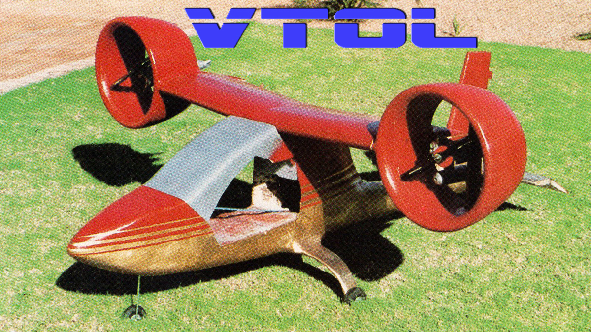
Model airplane engines inside shrouds are planned to power the RC test vehicle.
Most other forms of transportation—cars, cycles, boats, ships—can be operated at very low speeds. They can be stopped and reversed. But air planes must travel at relatively high forward speed.
A pilot flying a high-performance airplane that is new to him must fly the proper speeds in the traffic pattern or face the danger of stalls and spins. A novice pilot will feel like he is racing around the traffic pattern and be “behind the air plane” while he gets accustomed to it.
Helicopters overcome some of the limitations of airplanes. They are capable of flying forward, backward and sideways. They can lift consider able weight vertically and some have long hovering endurance. But they have limitations of their own. They are very complex and require much maintenance.
They cannot fly very fast due to the danger of encountering retreating-blade stall. Their relatively inefficient thrust does not allow them to travel many miles for each gallon of fuel. What is more desirable for many purposes is a type of airplane with VTOL (vertical take off and landing) capability.
In the 1950s and ’60s there was much interest in VTOL aircraft, resulting in a huge amount of money (primarily in military programs) spent on VTOL research and development. Once again there seems to be interest on the part of individuals and small companies in light V/STOL aircraft.
These machines have the obvious advantage over air planes of being able to land almost anywhere (although legal restrictions apply in many areas). Unlike helicopters, these aircraft are capable of high-speed cruise flight.
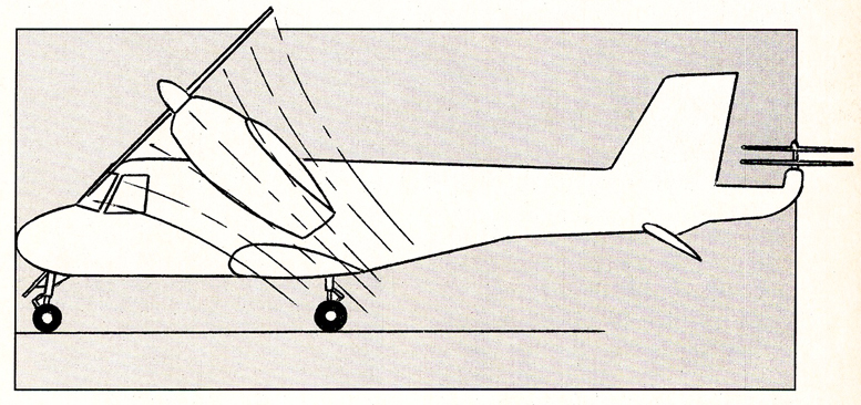
Figure 1. The wings are set at 45° in this drawing of a tilt-wing verticraft.
V/STOL aircraft offer potential for avoiding accidents because of their ability to fly at zero forward air speed. This is an especially great advantage in many countries where electronic navigation aids are few and far between. A pilot fearing he may be lost has an opportunity to land the aircraft and consider options.
Thunderstorm avoidance and poor visibility would not be so difficult with the capability of landing almost anywhere. The pilot would no longer have to fly around far off his intended course and face the danger of running out of fuel. Safety during instrument approaches may also be enhanced.
Defining the Terms
The term V/STOL should be clarified. It stands for vertical/short take off and landing. The abbreviation VSTOL has been used by some to refer to very short takeoff and landing aircraft, and this causes some confusion.
STOL aircraft achieve their low speed (and thus STOL performance) by use of large, lightly loaded wings and sometimes high-lift devices—full-span flaps, Fowler flaps, leading-edge slots or slats and large control surfaces.
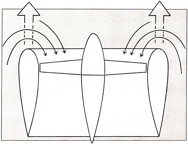
Figure 2. When a shroud is operating in a vertical position, air being pulled into the shroud from around the outside—easily demonstrated by tufting—helps create lift at the shroud leading edge.
Some of the two-place STOL aircraft kits currently on the market, have full-span auxiliary airfoil flaperons. These aircraft have relatively low purchase prices and operating costs, are rather simple to build and maintain, and can be used in bush flying operations.
But vertical takeoff and landing aircraft do not use these methods for achieving their performance. Although the vertical lift can be produced by a great variety of methods, it is not usually done by using large wings.
On the contrary, VTOL air craft wings are generally smaller than those found on conventional aircraft of similar gross weight. A large wing is not necessary because the takeoff and landing operations are accomplished through the use of powered lift systems.
The smaller wing partially offsets the extra weight of the VTOL power systems. Also, less drag is produced by smaller wings, thus allowing slightly higher cruise speeds for a given amount of power.
A high wing loading also contributes to a smoother ride in turbulence. So VTOL is not achieved by carrying STOL design methods to an extreme. Rather, they are completely different concepts.
The STOL operations of V/STOL aircraft are achieved by positioning the lift/cruise propulsion units at partial forward tilt rather than fully vertical. (See Figure 1.) The use of a short ground run allows a greater useful load to be carried. This is because wing lift as well as powered lift is used during takeoff. Not all VTOL aircraft are suited for STOL operations, however.
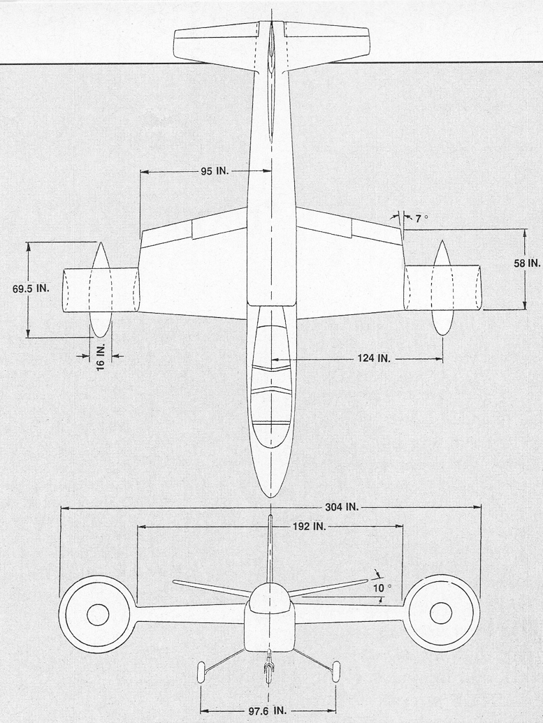
Figure 3. The Doak X-16 tilt-duct verti craft (circa 1958).
The Verticraft
Most V/STOL aircraft can be called verticraft, a term that refers to vertical takeoff and landing aircraft capable of high-speed forward flight but incapable of autorotational descent.
Most tilt-rotor aircraft are capable of autorotation, so they would not be classified as verticraft by this definition. Helicopters are capable of autorotation, but not high speed forward flight, so they are excluded from this definition on both counts.
A verticraft can be considered a type of airplane with vertical takeoff and landing capability. That is, it is much more similar to an airplane in general design configuration than to a helicopter. But this is an oversimplification and could lead one to think that a verticraft is merely an airplane with the added free benefit of VTOL capability. Unfortunately, however, there are prices to be paid for this additional capability.
One obvious VTOL requirement is that of additional thrust. For the aircraft to rise vertically, a thrust-to-weight ratio (T/W) of greater than 1:1 is necessary. Most light aircraft have small thrust-to-weight ratios. The required excess thrust must be in the form of larger engines, additional engines, thrust augmentation, or a combination of all three.
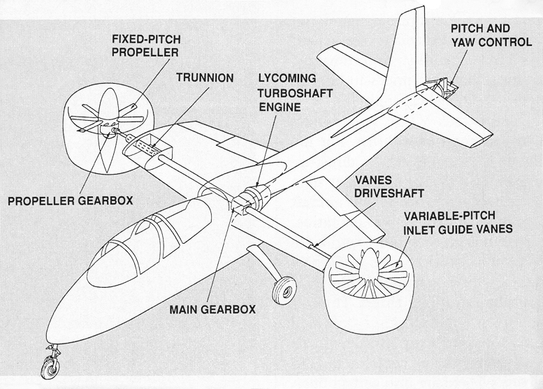
Figure 4. Doak X-16 control and propulsion systems.
This, of course, involves higher cost and increased complexity. (But verticraft don’t have to be as complex as helicopters.) There are also certain operational restrictions and other things to consider during VTOL operations. Among these are surface erosion (from prop blast) and possible ingestion of debris by the engines.
In addition to helicopters, there have been many different types of VTOL aircraft. Some of the early ones, turboprop and jet, were of the tilt-aircraft type. These high-powered single-seaters were parked vertically with their noses pointed straight up for takeoff.
After lift-off, the aircraft nose was slowly tilted downward, and forward speed was gained. When sufficient forward speed was reached the aircraft was placed in a level flight attitude and was supported by wing lift alone.
These were very difficult to fly and were largely impractical designs. Other verticraft had wing-mounted engines, and the entire wing was tilted about 90 to provide vertical lift. Known as tilt-wing aircraft, these initially experienced aggravated stall problems.
These difficulties were eventually overcome after much research, including a variety of tests involving different directions of propeller rotation. Other V/STOL air craft had fixed wings and only the tip-mounted propellers tilted. These designs had considerable complexity and/or thrust efficiency loss. Two V/STOL concepts considered in this article are tilt-shroud (or tilt-duct) and tilt-rotor.
Shrouded Propellers
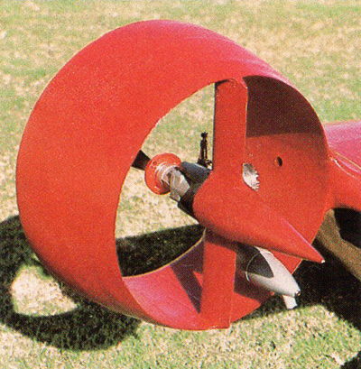
Shrouded propellers have proven to be advantageous on a variety of aircraft, not just VTOL designs. The relatively simple idea of placing a shroud around a propeller gives a number of advantages.
First, a shroud/propeller combination produces more thrust per engine horse power than does an open propeller, if rpm and propeller size are equal. A shrouded propeller can run efficiently at high rpm and produce a rather high velocity slipstream.
An ultralight engine driving a large, slow-turning propeller with a reduction drive may actually produce more thrust than a small shrouded propeller, but its slip stream velocity will be lower.
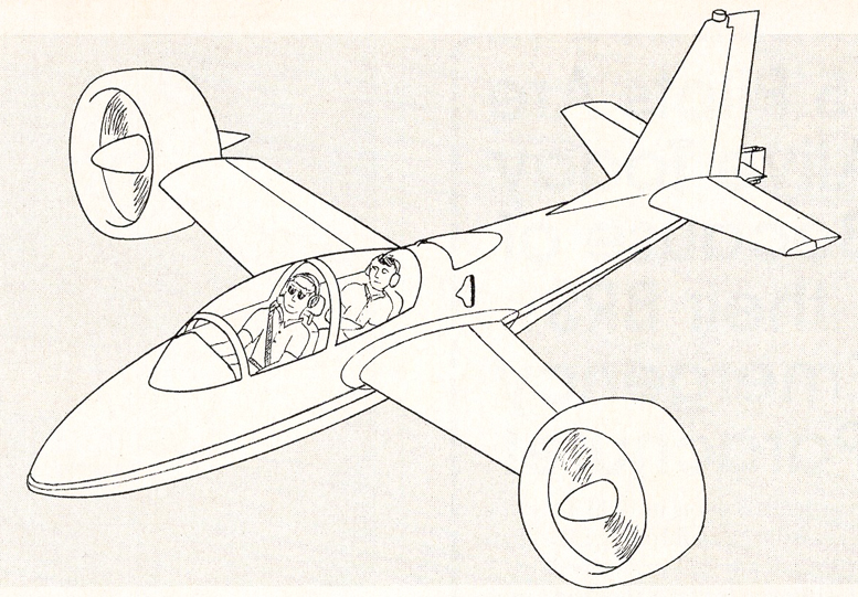
Figure 5. Possible homebuilt verticraft similar to the Doak X-16.
Second, a shroud reduces noise because it absorbs much of the sound produced by the propeller. This feature can be used to even greater advantage by placing properly designed acoustical panels in the inner surface of the shroud.
Third, the shroud helps prevent damage to the propellers. The possibility of gravel or other foreign objects striking the propeller blades is reduced.
Fourth, during ground operations, people will be less likely to come into contact with the rotating propellers.
When the shrouds are positioned for vertical takeoff, they produce an appreciable amount of lift. While the aircraft is hovering or being operated on the ground, air is being pulled up along the outer surface of the shroud.
As this air changes direction when it comes around the leading edge of the shroud, its velocity increases and an area of low pressure develops around the leading edge, contributing to lift. (See Figure 2.) One might expect this effect to be small.
However, results of tests on shrouded propellers show that this can give an increase in weight lifting capability of more than 20% over an open propeller of the same rpm and power. The efficiency of the shroud depends, of course, on its design and construction.
The Doak X-16
Perhaps the most exciting early V/STOL aircraft—at least for the homebuilder’s consideration—is the Doak X-16. This was a two-place, mid-wing tilt-duct research aircraft. It had two ducted fans, one at each wingtip. (See Figures 3 and 4.)
Power was provided by an 840-hp turboshaft engine located in the fuselage behind the tandem seats. The ducts were capable of rotating slightly more than 90°, from straight forward to 2° aft.
When the ducts were facing slightly aft, the rearward thrust provided some compensation for the residual exhaust from the engines, and it allowed maneuvering while hovering in a tailwind.
V/STOL Bell XV-15
To speed up the design and construction of its unique aircraft, the Doak company used standard aircraft components and design methods where possible. For example, the air craft used the fixed landing gear from a Cessna 182, and the duct rotation actuators were T-33 flap motors. The fuselage was of welded steel tubing construction.
A long tailpipe in the fuselage ducted the engine exhaust to exit through an opening at the rear of the aircraft. Mounted at this opening was a set of stainless steel vanes that were hinged horizontally and vertically. These cruciform-shape vanes con trolled pitch and yaw in vertical flight operations by vectoring the exhaust.
Control about the longitudinal axis (roll) during hover was achieved by varying the angle of the duct inlet guide vanes, which increased or decreased the airflow into the ducts. This action directly affected the amount of thrust provided by each duct.
Variation of the angles of the inlet guide vanes was accomplished by sideward motions of the control stick. A mechanical system gradually faded out the guide vane pitch changes as the ducts were rotated from vertical to horizontal (accelerating transition). At 0° duct angle, the guide vanes remained stationary and were not affected by movements of the control stick.
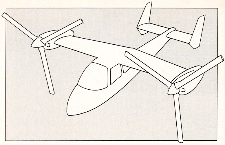
Figure 7. A four-place tilt-rotor veticraft might look something like this.
Control in forward flight was accomplished by use of conventional rudder, ailerons and elevators. These were connected to the stick and rudder pedals in the cockpit. An excellent feature of the X-16 was that the same cockpit controls were used in both vertical and aerodynamic flight operations.
This method of aircraft control developed by Doak was simple; it did not involve a collective stick or other helicopter-type controls as were used on many other verticraft. The X-16 did not require any automatic flight controls or stabilization, nor power boost.
The X-16 first flew in February of 1958 and performed very well. Initial testing for the military was done at Edwards Air Force Base. The Doak demonstrated conversions and re-conversions at various altitudes up to 6000 feet. Top speed was more than 200 mph. The X-16 had excellent acceleration capability.
Chase helicopters were not able to keep up with it during accelerating transition or the subsequent climb, even when the helicopter had a running start. The Doak could accelerate from zero forward airspeed in hover to 140 mph in 17 seconds.
One Doak engineer said that according to calculation, the X-16 could perform a short takeoff with a 500-foot run with a 50% increase in gross weight (above the VTOL gross weight).
Some of the performance figures of the Doak might not seem so spectacular in view of modem helicopters with similar power. The Hughes 500, for example, has exactly half the power and can carry five people. It has a top speed of 160 mph.
But the Doak certainly had excellent performance by 1958 standards, when Doak pioneered in this field. Remember that the X-16 was a research aircraft to prove the concept of tilt-duct VTOL aircraft. It had the fixed landing gear from a Cessna, and the design was not maximized for speed.
Updating the Doak X-16
Someone (or a small group of homebuilders) might have great success with a modern aircraft based loosely on the Doak design. With about two-thirds the wingspan and length, and composite construction, a tandem two-seater (Figure 5) would weigh about half that of the X-16.
Using carbon fiber, Kevlar and Nomex would result in a rather expensive structure compared to using Styrofoam and fiberglass, but the weight savings would be worth it. Avoiding the snow-balling effect of weight gain during design is especially important with vertical-lift aircraft.
This machine would have excellent performance with about 400 hp. This is still somewhat overpowered by airplane standards (though at least one homebuilt two-place airplane has been powered by a 420-shp Allison 250 turboprop engine), but this air craft could be operated at lower power settings in cruise.
Remember that there has to be some price paid for the incredible advantage of taking off and landing vertically. Mounting a single turboshaft engine in the fuselage (as in the X-16) would require shafts and gears for transmission of power, and that could be a weak point in the design. (A gearbox failure at one propeller would result in great asymmetry of thrust.)
If a suitable 200-hp engine could be found that is small and light enough, one could be mounted in each shroud, and cross-shafting between the engines would be used to provide power to both propellers in the event of an engine failure. A ballistic recovery parachute would also be advisable, though this would not provide protection below about 50 feet of altitude.
The Tilt-Rotor
The tilt-rotor is another V/STOL aircraft concept that has been used successfully, though it is more complex than the tilt-shroud type. The Bell XV-3 was a 4800-pound-gross-weight tilt-rotor that made its first flight in 1958. Two prototypes were tested rather extensively, but this design was found to have some stability and control problems.
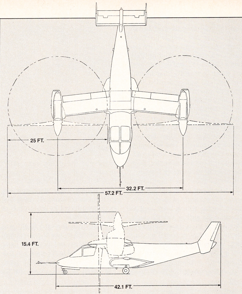
A later design, by Bell Helicopter Textron, was the XV-15, which made its first flight in 1977. This high-wing air craft has one tilting engine/rotor nacelle at each wingtip. (See Figure 6.) Each turbine engine produced 1550 shp (with an emergency rating of 1800 shp), and each rotor is 25 feet in diameter.
The XV-15 uses conventional air plane-type controls for horizontal flight and helicopter-type controls for hovering flight. Full-span flaperons are used for roll control in for ward flight. The elevators and rudder are controlled by a stick and pedals in the cockpit. These are functional at all times, though they have no effect until sufficient forward speed is attained.
In hovering flight, aircraft pitch is controlled by cyclic pitch variation of the rotor blades. Roll control is achieved by collective pitch changes differentially between the right and left rotors. Yaw control is accomplished through opposite cyclic pitch variation between the left and right rotors. No tail rotor is required for any of these actions.
In the XV-15, the engines are cross-shafted so that if one engine fails, the operating engine will drive both rotors. Power is cut in half, but with the emergency power rating of the engine, the aircraft can still make a safe vertical landing on one engine.
Even in the event of total power failure, this aircraft can make a power-off autorotational descent. An inoperative engine can be disengaged through a one-way clutch. An ejection system is also provided for the crew; safety is obviously a high priority in this design. The even larger V-22 Osprey has the same basic design configuration, but has more than 6000 hp per engine.
The XV-15 can accelerate from 0 to 300 mph in only 28 seconds. It has reached a top speed of 348 mph, and accomplished more than 2000 transitions between vertical and horizontal flight. It has made many public flight demonstrations.
The tilt-rotor is probably the only VTOL concept that could use a four-stroke piston engine. Such engines weigh too much for aircraft with high disc loadings, such as tilt-wing or tilt-shroud designs.
But the large rotors of a tilt-rotor design have lower disc loadings, moving larger air masses (though at lower velocities) than do the other designs. A lighter type of engine would still be desirable, however, even with this concept.
Homebuilt Tilt-Rotor
A possibility for a four-place homebuilt tilt-rotor design is shown in Figure 7. Such an aircraft would require at least 200 hp per engine. A two-place tilt-rotor would probably be a better size to start with. Here again the engines should be cross shafted for engine-out safety. The autorotational capability and a ballistic recovery parachute would also contribute to safe operation.
Designing and building a high speed V/STOL aircraft is certainly not a one-person project. Even more than conventional airplane designs, these aircraft will require far more money, time and work than originally anticipated.
Wind tunnel testing and/or flying a one-quarter scale RC model would be a good idea before risking a flight in an unknown design with someone on board. Also, it’s best not to install an experimental engine in an unproven airframe.
It’s a long lonely road. Several people in Australia were killed trying to fly VTOL aircraft of their own designs. Before beginning such a project, it’s wise to obtain as much information as possible.
Some university libraries are good sources of additional information. A successful small V/STOL design would start another revolution in the homebuilt aircraft industry. At least two small companies are working on it.
Much of this article has been excerpted from the new book V/STOL Design Concepts for the Custom Aircraft Builder, Second Edition, by Philip Terpstra.

Be the first to comment on "Coaxial vs. Conventional Helicopter & Tilt-prop VTOL Designs"