
Helicopter Main Rotor Systems
DYNAMIC ROTOR ADJUSTMENTS WITH POWER
Wouldn’t it be just great if the first time you ran your blades up to 350 RPM your helicopter was as smooth as a sewing machine? It would be nice, but you wouldn’t learn anything! If something happened to your ship that made it rough, you wouldn’t know where to start or what to do.
I know a handful of good helicopter pilots. They can do a fairly good preflight, and when their teeth start to chatter, they know they’d better get the helicopter to a good A&P mechanic . . . if the ship will make it there. They have come to expect the arm-and-a-leg bills associated with any work done. And most times, work done isn’t work done right.
These pilots don’t know a pitch horn from a muffler bearing. How much better off we homebuilders are! We built it, we rigged it, we adjusted it, we tested it, we maintain it. How lucky can we get?
How in the world the FAA saw fit to put us in this grand position, I will never know. Let us not abuse this privilege we have and try to hold on to it. Otherwise, the ordinary man (that’s us) with his dream for his own helicopter, could never own one.
The cost to own and maintain a factory-made and certified helicopter is prohibitive unless you can justify it for business and get a write-off. Our friends in Canada can’t build and fly a helicopter at this time. Let us hope that sometime their officials will change this ruling for them.
WHAT TO LOOK FOR
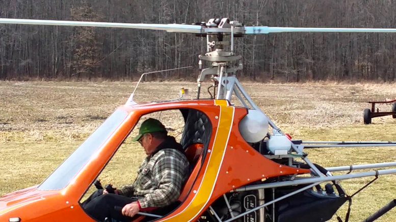
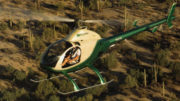
We are talking about the Scorpion here, but this technique will apply to other two-bladed, semi-rigid rotor systems with a welded tubing tail boom that isn’t firm and rigid.
(The new Exec with the round tail boom rigidly attached to frame will have its own way of fine-tuning the main rotor.) Why am I talking about the tail boom here when we are talking about the dynamic adjustments of the main rotor? Simple!
The tail rotor shaft area on the end of the tail boom is what you watch to tell you what is out of adjustment. A lateral movement, lead-lag is off. A vertical movement, blades are out of track. A diagonal movement, out of balance.
Before we start and run up for the first time, do this: Mark collective handle position with tape where blades are at a 3-degree positive pitch. Check on blade straps with protractor. DO ALL RUNUPS AT 3 DEGREES POSITIVE PITCH.
Do this in a no-wind condition. Start your engine, engage your clutch and let warm up a few minutes. Slowly increase throttle and bring rotor RPM to 300. If tail shaft area is not shaking too bad, increase RPM. Somewhere between 350 and 400 the movement will be the worst.
(This 350 to 400 RPM range is hard on your ship, but not if you don’t hold it there for extended periods. Hold it there long enough to know which direction the movement is most pronounced.)
Make sure your cyclic control is as near to its neutral position as possible, which is swash plate 90-degrees to main shaft laterally, and fore and aft. Glance out at blade tips. Tips should be tracking through the same slot of air.
If they are not pretty close to each other, shut down and bring to a stop with master blade out over tail. (Get in this habit of stopping master blade out over tail, this puts the cable and links toward pilot side.) Adjust slave blade link only, if blades were not visually in track.
Get this as close as you can now, just by sight; later on we will get it perfect with a greased brush on the end of a stick. Run up again to see if you helped or made worse the slave blade link adjustment. Keep at it until the blades look in track.
DYNAMIC LEAD-LAG
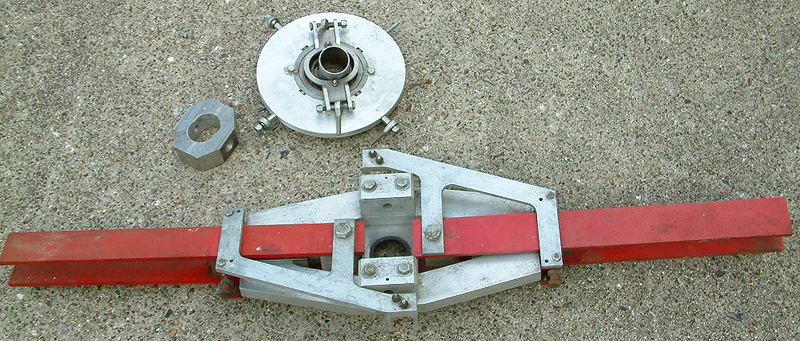
On the next run up, hold 400 RPM and glance up at main rotor shaft near hub. If lead-lag is out bad, you will see the main shaft shake an eighth-inch or more. If you saw your main shaft had a shake and the tail boom area had a noticeable lateral movement, work on this next. Attach a dial indicator on master blade straps with pointer on outside edge of aligner blocks.
Loosen the two aligner block bolts slightly and adjust quarter-inch bolts to shift blade .002 toward lead edge. Re-torque block bolts. I like to loosen half-inch retention bolt, hold blade coning angle, reset thrust block flush to inside of hub, then re-torque this bolt.
You don’t have to with every small adjustment, but I do. Be sure to keep a written record of your adjustments. You will probably make quite a few trial and error adjustments. If you don’t keep a written record, you will soon be lost and have to go back and static lead-lag it again.
When ready, run your rotor system up to 350-400 RPM. Did the adjustment improve or worsen the lateral shake? If it improved it, shut down and go another .002 with same procedure. If it made it worse, you will need to move master blade toward the lag direction.
Move it in the lag direction .004 from where you are now. Lead or lag master blade until main rotor is as smooth as you can get it. Then repeat this same procedure on slave blade until all lateral movement in tail boom area is stopped at 400 RPM.
This will take time and patience, but you are learning valuable experience that will put you way ahead of the average helicopter owner. I have observed many homebuilt helicopters, and somebody has not known how, or taken the time, to get these adjustments right.
DYNAMIC TRACKING
At 400 RPM and 3-degrees positive pitch, look out again at the blade tips. Are they tracking in the same slot of air, or is one a little lower than the other? Make a tracking stick about four feet long with a small paint brush taped on the end.
Have a helper sit on the ground in view of you, with a little grease or paint on the brush. At 500 RPM and 3-degrees positive pitch, nod to your helper to raise stick slowly until brush just nips rotor, about a foot in from tips. Shut down and see if both blades have a mark on them. If just one has a mark, it is lower.
Let master blade pitch link alone. Raise or lower slave blade only to match master. The reason is, the master blade is set for your 1 ½ – degree negative setting with collective full down, and we don’t want to change that. Keep at it with the stick until you see an equal mark on both blades.
This adjustment will be a trial-and-error, so get it right. Remember, an out-of-track condition will cause an up and down movement in tail rotor shaft area at 400 RPM and a one-per-rev hop in cabin area.
DYNAMIC BALANCE
An out-of-balance condition will give a diagonal movement in the tail rotor shaft area. If you have this, try a small wood screw in one blade tip. Run up to 400 RPM and check for improvement.
Again, trial-and-error on one blade or the other will correct this situation. You may need a screw and a couple of washers — whatever it takes.
By now your rotor system should be ultra smooth. From engine idle all the way up to 500 RPM with no movement in tail boom area. If you have accomplished all this on your own, you are on your way and, I will add, in the minority!
STILL NOT SMOOTH?
Here are some problem areas that could prevent you from achieving smoothness in your rotor system. Just don’t get discouraged.
Check these out:
-
Swash plate not accurately leveled to hub laterally. They must be perfectly level with each other. Very important.
-
Swash plate universal not spaced equally on main shaft. Check with dial indicator on swash plate for no more than .003 run out while rotating main shaft 360°.
-
Lateral shims in hub universal not equal.
-
Fore and aft shims in hub universal not equal. (Both No. 3 and 4 problem could keep a rotor from being smooth. Check shims with micrometer.)
-
Excess play laterally, or fore and aft way in hub universal. .002 play is right. Check that holes in hub walking beam are equal from center.
-
Check location of half-inch hole in relation to leading edge of blade. Measure from center of hole. One and seven-eighths inch is right. If off, both blades must be equal measurement.
-
No lateral play in swash scissors.
-
Check the measurement on pitch horns from center of half-inch bolt to center of quarter-inch bolt. Both horns must have same moment arm. The master pitch horn is angled down.
But distance from hole to hole must be the same. If one was longer, it’s moment arm would give that blade less pitch, then its partner on up collective.
-
Check at full up collective, positive blade pitch should be twelve degrees. Put protractor level on blade straps to check. Check other blade, you can be off one degree from its partner, but no more.
Rework one pitch horn if off to achieve within a half-degree of each other at full up collective. Some guys tell me their ship is smooth until they start to raise collective. This problem could cause this.
-
All four wood filler blocks on main blades must be in level plane with chord line of blades. So, as you can see, there are many things than can prevent a smooth rotor system. By the process of elimination, you should be able to work out your problems. Good luck from Helicopter Ed!
DRIVEN ROTOR TIDBITS
Bernadine and I started our 1981 activity by attending, with our ship, the Ohio Division of Aviation Helicopter Seminar at the Ohio State University Airport, April 23 and 24. This was a big one! About 25 different helicopters showed up and most were under one roof.
Seminars were held every hour throughout the two days and a huge banquet on Saturday night. Guest speaker after the banquet was Igor Sikorsky’s oldest son, Sergei.
He had film clips and stills of every machine his famous father ever made. Every helicopter enthusiast was thrilled and very impressed with this great man’s accomplishments.
Manufacturers represented were Aerospatiale, Bell, Enstrom, Hughes, MBB, Robinson, Rotorway and Sikorsky. We thoroughly enjoyed our weekend, met lots of wonderful helicopter people.
Kemp Glanville and son, Ed, of the Glanville Sky Master, from St. Thomas, Ontario, Canada, surprised us with a stopover enroute to the EAA Sun-N-Fun fly-in at Lakeland, Florida.
They stayed overnight, so we had time for a good visit with them. Time, too, to take them to meet our gyro friends, Curt and Evette Steele. A lot of you guys who were active in the 1960s know Curt.
He designed and built a superior gyro head and manufactured many. Most of them are still flying after a decade or more. Kemp and Curt have something in common — both love the gyro and know the direction to go is jump-take-off capability, with collective pitch control.
So let us hope these gentlemen with the brains and machine shops can work out a simple, foolproof, safe system to make this possible. A gyro with a no-roll takeoff, two or three passenger capacity is the dream of many home builders.
It is going to be interesting! You will hear more of Kemp and Curt on these pages of PRF. As of this writing (late May, ’81), Webb Scheutzow has completed his “Stork” weight shift control ultralight helicopter. He hopes to begin testing very shortly.
This should prove to be very interesting. Webb held seminars at Sun-N-Fun. He is very knowledgeable on helicopters, with the Scheutzow Hawk and Bee to his credit. I hope and pray he will contribute some good meaty stuff for us in PRF sometime.
About three months ago I asked Mike Hynes of Brantly-Hynes Corporation to contribute some information to us helicopter guys. I know you are busy, Mike, but I am still watching the mail. Two of our well-known PRA gentlemen have Brantlys — none other than your friends and mine, Ken Brock and George Charlet.
We just returned from a great weekend in Mayville, New York. That is the home of Bob Dart’s International Helicopters Inc. His 2nd Annual Rotorcraft Convention was held Memorial weekend, May 23 and 24. A lot of helicopters and rotorcraft people came.
Helicopters were flying non-stop from morning ’til night, both days. Bob Dart was in the air the most with his new Commuter II B. It sure looks and flies good. He even let Helicopter Ed fly their ship! The pilot gave me the cyclic first, then the collective and throttle, then the foot pedals. After five minutes, I was on my own.
I lifted off, made turns, went forward and backward, and landed, over and over. I was amazed now easily I adapted to his machine. They offered helicopter rides and many took them. Bob Dart was the perfect host. Made us campers feel at home.
Had a banquet for us all Saturday night and had the factory open to everybody, both days. If Bob holds his 3rd annual Convention next year, watch these pages for information early in ’82. More pictures of this event in the next issue.


Be the first to comment on "The Driven Rotor"