
Bensen B9 Little Zipster Helicopter – From Wikipedia, the free encyclopedia.
“The Bensen B-9 Little Zipster was a small helicopter developed by Igor Bensen in the United States in the 1950s and marketed for home building. Similar in general configuration to Bensen’s previous rotor kite and autogyro designs, it consisted of an open aluminum framework but substituted the autorotating main rotor for a coaxial, counter-rotating system of two, two-bladed rotors. A large tailfin provided directional stability, and the aircraft was controlled by a handlebar system extending over the pilot’s head to the rotor hub.”
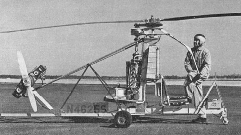
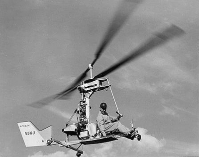
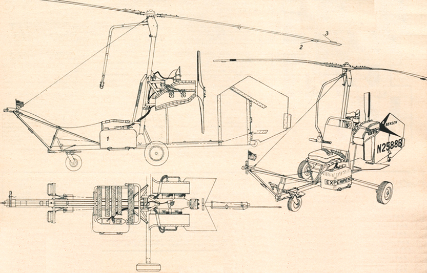
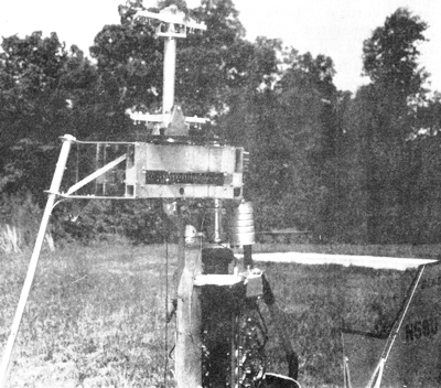
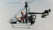
Dr Igor Bensen, inventor of the “Gyrocopter” developed a number of rotary wing configurations, one of which was a coaxial rotor helicopter. The “Little Zipster” was a simple coaxial design which utilized construction methods and components from the Gyrocopter. Plans and kits were offered in the late fifties, but we have not heard of anyone who built and flew one, although the prototype did fly as illustrated by the included photos from an original Bensen information pack.
Igor Bensen Coaxial Little Zipster Helicopter
The Little Zipster design included new concepts that departed from the normal helicopter, but the ship supposedly flew well in spite of the fact that it did not confirm to traditional helicopter configurations. The main difference was that it utilized counter-rotating, coaxial rotors.
Coaxial rotors is a configuration that has never been applied to a production helicopter in this country, although Igor Sikorsky built a coaxial design before he immigrated to the U.S.
There are several advantages to the coaxial design, but U/S manufacturers tended to stick to the conventional single rotor with tail rotor except for Kaaman which produced an inter-meshing rotor design, and Piasecki and Boeing which have produced tandem rotor ships.
Advantages of the coaxial rotor helicopter are:
-
Simplicity; short couplings from the engine to the power train, and the airframe can be very compact and lighter weight than conventional designs.
-
There is no torque on the airframe since the rotors rotate in opposite directions and therefore, no power-robbing tail rotor is required.
-
There is no dissymmetry of lift in forward flight since there are always advancing and retreating blades on both sides of the airframe at the same time.
-
In hover the lift force is purely vertical – there is no side force generated due to the absence of the tail rotor.
The positive features of the coaxial rotor helicopter led early pioneers to select that design, but there were also some disadvantages that discouraged helicopter companies from producing such a configuration.
Some of the disadvantages are:
-
Complexity of the control system. Most helicopters utilize the conventional swash plate and coupling the joystick to the swash plate system of two rotors rotating in opposite directions increased the complexity and reduced reliability.
-
Control reversal at partial power. When collective is reduced significantly in a coaxial rotor helicopter, rudder pedal action is reversed. This reversal is caused by differential collective when changing from power to autorotation modes. (The primary method used to control yaw was to increase collective on one rotor or the other which caused torque on the airframe in the desired direction).
-
Blade interference. This was a sever problem encountered by helicopter pioneers since many didn’t realize how much the rotor blades flapped during flight and if insufficient spacing between the two rotor disks was used there could be a collision in flight.
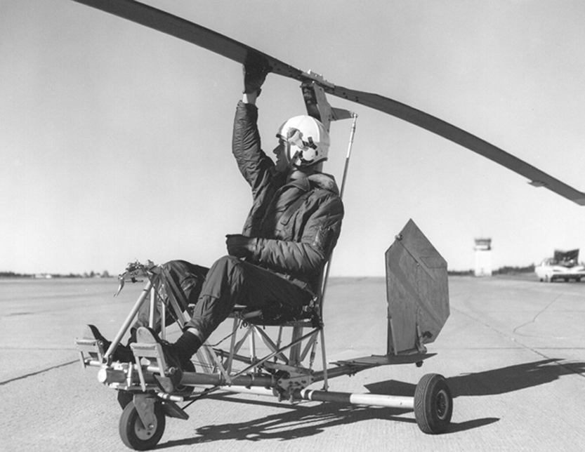
Little Zipster helicopter front view
According to Dr Bensen, all these disadvantages were overcome in the Little Zipster design and complexity was reduced to a bare minimum.
First of all, the rotors were of unequal diameters and they turned at different speeds. This was one of the major design improvements over the typical coaxial rotor design.
The upper rotor had a diameter of 22 feet turning at 300 Rpm while the lower rotor was 20 feet in diameter and rotated at 330 Rpm.
The main purpose for unequal rotor diameters was improved lift. In coaxial rotors with equal diameter rotors the lower rotor operates in the downwash of the upper one which reduces the efficiency.
Little Zipster helicopter close-up
The same is true with counter-rotating propellers – the rear prop is more efficient if it has a slightly smaller diameter so it is not operating in the tip vortices of the front one. In a properly designed counter-rotating prop configuration increased efficiencies of up to 6 percent can be realized, and it probably applies to helicopter rotors also.
The rotor blades on the Little Zipster were of wooden construction with a steel spar – essentially identical to the wooden Gyrocopter rotor blades that were common on Bensen ships for several years.
The air foil was similar to the 8-H-12 helicopter air foil which has a flat bottom and very near zero pitching moment.
Again, borrowing from the Gyrocopter, the rotor system utilized a teetering type head which required no lead-lag or flap hinges. Pitch was also fixed, therefore no collective control was utilized which further reduced the complexity and weight.
Since the Little Zipster was designed for low level flying no autorotative capability was considered necessary. Changing from powered flight to autorotation while in a hover requires some 200 – 300 feet of altitude anyway, so if one stayed close to mother earth it was relatively safe. A two position collective was planned for later, but to our knowledge it was never implemented.
The upper rotor was driven by a long shaft which separated it from the lower rotor.
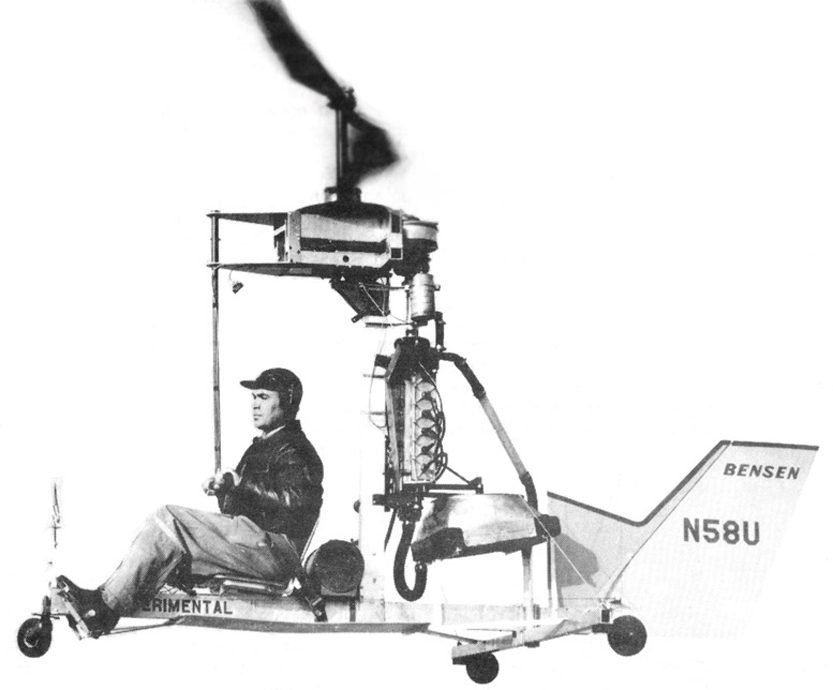
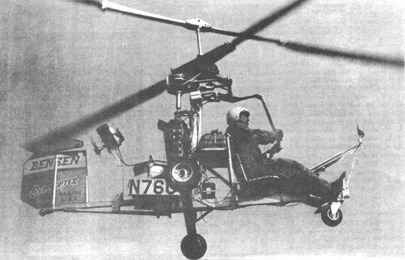
Flying the Little Zipster helicopter
Both rotors were driven by large sprockets which in turn were driven by the differential transmission. Chain drive was chosen because of less expense, complexity, and weight over a gear system. The chains were recommended to be replaced after 200 hours of operation. An updated version of the Little Zipster could utilize cog belts instead of a chain drive for better reliability and TBO.
The rotor head was attached to the mast via a universal joint which allowed it to tilt fore-and–aft and side-to-side, providing normal cyclic functions without the complexity of a swash plate system.
The transmission was mounted on the rear section of the rotor head. The transmission was unique in that it was a differential drive which totally eliminated torque on the airframe by allowing the two rotors to vary in speed.
The effect was the same as a tip-jet powered rotor and it required no tail rotor. A large rudder with its hinge axis slanting rearward produced yaw control from the downwash of the rotor blades.
The clutch in the Little Zipster design served two purposes. First, it acted as a freewheeling mechanism, and secondly, it smoothly engaged the driving power from the engine to the transmission by centrifugal action after the engine was started.
The unit utilized friction shoes which lead the direction of rotation and produced an extra bite and force multiplication during engagement. If the engine stoped or slowed down below the speed of the rotors, the clutch drum would automatically override the shoes without producing drag on the rotors. Medium soft brake shoe lining was used to prevent chatter during engagement.
The clutch required no manual controls nor any attention from the pilot. It automatically reached full engagement at 2500 engine Rpm and remained engaged as long as the engine was running at speed.
The power plant for the Little Zipster was a two stroke, waster cooled, 70 Hp Mercury outboard boat engine. Several outboard engines of 60-70 Hp were listed as practical for the Little Zipster.
A Jeep radiator and a fan driven by a V-belt was used to keep the engine cool and a light batter provided power for the ignition and an integral starter system.
The Bensen B9 Little Zipster helicopter
Instrumentation was very basic: airspeed indicator, engine tach, water temperature gauge, and a drift flag. No enclosure was planned since the Little Zipster was to be used for low and slow flying.
The information manual even included instructions for learning to fly the ship. Details included hovering, slow flight and high speed flight. Bensen made it sound simple – he stated that anyone who could drive a car could learn to fly the Little Zipster.
Why this simple helicopter never materialized is puzzling. It appeared to be a sound design and that was easy to build and simple to fly. Perhaps it was too expensive for the average rotorcraft enthusiast as are most helicopter kits today. The typical would-be rotorcraft pilot wants a pure helicopter at the cost of an average, open frame gyroplane – you just can’t have your cake and eat it too.
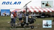
There is no reason why this basic configuration couldn’t be a practical aircraft with today’s technology. In fact the Nolan brother in North Florida have developed a similar configuration.
A little about Dr. Igor Bensen – (more on the Little Zipster after..)
Courtesy: JCM Services.
Igor Bensen founded the Popular Rotorcraft Association (PRA) in 1962. Most don’t realize that PRA was founded as was their magazine, or journal, as an advertising medium for Bensen to sell his gyrocopter. This is much as what the National Geographic Society does with its magazine.
If you want to buy the National Geographic magazine your payment becomes “dues” for joining the National Geographic Society. Bensen did the same. If you look at the original PRA magazines they were essentially two and three page flyers for selling the autogyro variants such as the B6, B7, and finally the B8 and B8-M.
The PRA is now the non-profit interest group for owners and homebuilders of autogyros and helicopters, based in Mentone, Indiana.
Bensen coaxial gyrocopter helicopter
Igor Bensen, born in 1917, was the son of a Russian agricultural scientist, Basil Mitrophan and Alexandra P. Bensen. His father was posted to Czechoslovakia in 1917 at the beginning of the Russian Revolution while the rest of the family remained behind.
The Russian civil war lead to harsh times, and the Bensen family was soon reunited in Prague, far from the turmoil. At 17 Bensen was sent to the University of Louvain in Belgium, from which he received a B.S. degree.
Bensen accepted a scholarship from the Stevens Institute in New Jersey in 1937 to study mechanical engineering, graduating with honors in 1940. As an alien Bensen had been forced to turn down a job offer to work for Igor Sikorsky, and his first job was as an engineer with General Electric at the age of 23. General Electric executives took notice of Bensen’s interest and assigned the young engineer to the company’s helicopter development efforts.
While working on the project, Bensen flew a salvaged Kellett XR-3 in 1943, and eventually gained almost exclusive use of the surplus Autogiro. Bensen became a highly skilled Autogiro pilot, and gained a deep understanding of the dynamics and theory of autorotational flight. The USAAF (United States Army Air Force –actually the Air Corps) had received some of the recovered FA-330 rotary kites and were experimenting with pilot George Townson, as well as a Hafner Rotachute and Bensen asked his boss to acquire the Rotachute for evaluation.
The military agreed to loan the Rotachute providing that General Electric agreed not to fly it. Bensen ignored the military’s requirements and personally flew the Rotachute in tow, and launched it from the bomb rack of the XR-3. Those tests lead to the Bensen B-1, an amateur-built 120 Ib giro-glider capable of carrying a 300 Ib load, differing from thee Rotachute with the addition of nose and tail wheels, a semi-rigid rotor in place of the Rotachute’s individual flapping rotor blades, and a control stick ‘reverser’ to allow more effective direct-control of the rotor.
Bensen gyroglider
The crash of the B-1 led directly to the B-2 which was of an all-metal construction. The B-2 lead to the G-E Gyro-Glider in November, 1946 but little came of the G-E model. And subsequently in Schenectady, the Helicraft Equipment Company developed a 60 Ib variant of the Rotachute called the Heli-glider in 1949. An extremely simple design that flew with a 14 ft rotor that achieved 550 rpm, the lack of weight made it difficult to fly with an overhead stick control, and the project was soon abandoned.
Bensen, now firmly committed to rotary flight development, joined Kaman Aircraft in 1951 where he organized and directed the research department and flew Air Force and Navy helicopters. After two years, borrowing money from his brother, Bensen left to found his own company in Raleigh, North Carolina.
In 1953 Bensen Aircraft Corporation introduced the B-5 Gyro-Glider, a single-seat rotary-kite towed in back of a vehicle and deriving its lift from an unpowered rotor. It featured a light tubular aluminum frame resembling a cross with two pieces, a longer keel crossed by a shorter perpendicular section. A lightweight aluminum-frame web set was attached to both the keel and a reinforced metal mast extending upward from the keel. Control was initially achieved with a hanging stick control attached directly to the rotor hub that was positioned on top of the mast with a two-blade rotor.
A nose wheel was attached directly to the front of the keel while landing wheels were affixed to each end of the perpendicular crosspiece. The keel, in back of he seat and mast, carried a plywood fin and rudder much as had the Rotachute. It flew well when towed by even a small automobile and did not require any license, and was relatively safe. It was also distinguished by ease of construction and the builder could either purchase a kit or build from plans. The materials were readily obtained and fabrication could be completed by the moderately skilled in 3-4 weeks. It would become the home-built B-6, and the prototype was accepted into the Smithsonian’s NASM on July 22, 1965.
Bensen subsequently developed a Reynolds aluminum prototype, the B-7 Gyro-glider which flew on June 17, 1955. From B-7 .came the B-7M (for motorized) which first flew on December 6,1955 with Bensen as pilot and Charles “Charlie” Elrod and Tim Johnson as ground crew. It weighed 188 lb. as the airframe was made of rounded aluminum tubing and had a wooden propeller attached to a 42 hp Nelson two-stroke engine, with the wooden rotor attached to a spindle type tilting head cyclic pitch rotor with a hanging control stick. Bensen called his Rotachute-derived creation a Gyrocopter, a term he subsequently trademarked.
Bensen B8M gyrocopter
After three days of successful flight testing the B-7M crashed as its pressurized fuel tank failed. Bensen, a highly experienced Autogiro pilot, set the aircraft down in woods adjacent to his NC factory. He later ascribed the safe landing to “much luck and the good Lord’s will.” The B-7M, rebuilt in three days, was flying by December 17, 1955, a particularly moving experience for Bensen as that was the 52nd anniversary of the Wright brothers first powered flight.
Bensen relentlessly analyzed the flight performance of the B-7M, particularly those factors that had led to the accident, and the result was an improved control linkage to the rotor head. The subsequent B-8M model, incorporating the improvements developed and tested in the B-7M, powered by a more powerful 72 hp McCulloch two-stroke piston engine that had been used on drones for the military, was placed into production in 1957 and became the most produced and copied aircraft Benson B8M design in history and provided, in kit form and plan-built, the most popular way to fly.
The “Spirit of Kitty Hawk”, a B-8M Gyrocopter in which Bensen had personally duplicated the Wright brothers historic first flight at Kitty Hawk on December 17, 1966, and with which he had set twelve world and national Gyrocopter speed, distance and altitude records between May 1967 and June 1968, was accepted into the Smithsonian Institution aviation collection on May 14, 1969. The Bensen, and its variants and local adaptation was to dominate the American Gyrocopter movement for almost twenty-five years.
Some of the above is an excerpt from Dr. Bruce H. Charnov’s informative book “From Autogiro to Gyroplane”.
Other text and photos are not from his book but from Google searches and from the Groen Brothers Aviation Website on the history of the gyro — http://www.groenbros.com/history.php Bensen used his Popular Rotorcraft Association with its magazine to sell his gyrocopter. He also pushed for a “gyro in every garage” and advertised in many popular magazines such as Mechanix Illustrated and Popular Mechanics.
In the 1950s Bensen Aircraft Corporation exploded upon the sport aviation scene with their ground-breaking “Gyrocopters” and “Gyrogliders.” When the brilliant engineer behind this success, Dr. Igor Bensen, introduced the B-7 Gyroglider (1955), its unprecedented simplicity of design and ease of flight captured the public’s imagination. Although the B-7 had no engine and was towed into the air very much like a kite, shortly thereafter the engine-powered B-7M Gyrocopter was introduced and a new age of powered homebuilt aircraft dawned. Dr. Bensen’s revolutionary designs have been copied and modified, but, in the opinion of many, never surpassed.
The Bensen Aircraft Corporation was established by Dr Igor Bensen at Raleigh-Durham International Airport in North Carolina in 1952 to develop and market a variety of helicopters and autogyros of Bensen’s own design. The most successful product was the Bensen B-8 that first flew in 1955 and remained in production until the company closed down in 1987.
| SPECIFICATIONS OF THE B-8M GYROCOPTER | |
|---|---|
| Height | 6.5 ft |
| Length | 11 ft |
| Empty Weight | 250 lbs |
| Gross Weight | 550 lbs |
| Payload Weight | 300 lbs |
| Rotor Diameter | 20.5 ft |
| Disc Loading (lbs/sq ft) | 1.6 |
| Engine (original) | McCulloch 4318 |
| Horsepower Range | 65 to 90 |
| Maximum Speed | 95 mph |
Some may ask about the reason for focusing on Bensen when now there are all these fancy gyroplanes?
“Never forget the importance of history. To know nothing of what happened before you took your place on earth, is to remain a child for ever and ever.”
Igor Bensen’s gyrocopters were the focus of gyroplane history from the early 1950s until the late 1970s. When his company closed, Ken Brock, the Bensen salesman on the West Coast, took over the lead with his KB series of gyros which were then the leading gyros until the many seeds planted by Bensen took root and led to the dozens of gyro types, some of which grew, and others died after being around for just a few years.
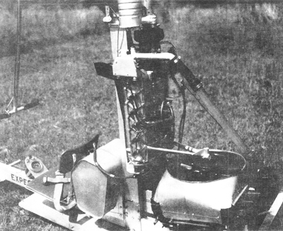
Bensen helicopter rotorshaft
We will include details of the rotor head, blades, and transmission on the next few pages.
As we mentioned previously, the Little Zipster coaxial helicopter is a unique design which could possible be updated with todays technology.
Modern helicopter items such as light weight two stroke aircraft engines, metal rotor blades, and polychain style cog belt drive systems.
The helicopters differential gear box for the main rotor blades is the only item that would not be readily available off-the-shelf, but perhaps there is one available that would do the job.
We will do a little research on the Little Zipster to see if we can’t find a usable unit in case anyone is interested in undertaking such a project.
Bensen B9 helicopter mechanics
We have been covering the Bensen B-9 coaxial rotor helicopter in the last few pages and this issue concludes what information we have on the unique ship.
There is an independant article on the next pages which asks many questions of this unique design, an interesting read!

Hovering the Bensen helicopter
Dr Besen developed a total of 18 prototype gyro and helicopter configurations over the years – an enviable achievemnt.
Seven different gyrocopter designs were developed including the B-8H hovering gyrocopter which was a combination of the B-9M Gyrocopter and the B-9 Little Zipster helicopter.
Bensen flew the B-8H prototype in June, 1973. It was the first successful flight of a counter-rotating aircraft towed in autorotation.
The B-8H used two engines – one to power the counter-rotating rotor blades and a smaller engine driving a pusher prop which provided forward thrust and plenty of high velocity air over the rudder for good yaw control.
With sufficient power to the rotors to provide lift, very little power is required to provide adequate forward thrust for a 50-60 Mph cruise.
According to information in vintage aviation magazines the B-8M Gyrocopter could be converted to the “H” model, but we have never heard of any conversions or kits flying. Drawings of the B-9 are dated 1959 while the B-8H hover-gyro was first flown in 1973.

Bensen zipster helicopter
The B-8H hover-gyro appears to have the same basic drive train to the rotor system, and the airframe appears to be almost identical except for the vertical stabilizer and rudder.
One interesting point to note in the centrefold drawing is the “delta-three” teeter hinge arrangement. We saw the same configuration in the Whistler RC autogyro.
The teeter axis on a normal rotor system is perpendicular to the span of the rotor, but the delta-three configuration rotates the teeter axis 15 degrees away from perpendicular in the direction of rotation.
This unique configuration supposedly reduces the amount of teeter which would be a desirable feature on a coaxial rotor system. It should also allow increased top speed.
VIDEO : Jolly Glider One Man Gyrocopter helicopter archival newsreel stock footage
Note from Mr Zorn: The articles on the Little Zipster were especially interesting. I began looking at the design and thinking it was too bad it was never accepted. The next thought of course was: “Why not,?” After looking at it for a while, I began to see some possible flaws and possible improvements. Since I am always short of time and money I don’t expect I’ll ever try to build an aircraft with these changes.
The next best thing seemed to be to pass the idea along. There are not many people that get excited about small rotary wing aircraft. So the next best thing: I wrote this article.
I have written my article with a questioning style in the hopes that awe might get some readers to come forth with their ideas, not only about the Bensen B9 Little Zipster helicopter, but about other designs, old and new.
Bill Zorn is an instructor at the Gulfstream Commander Learning Centre in Bethany, Oklahoma, USA.
| SPECIFICATIONS | |
|---|---|
| Crew | One pilot |
| Length | 11 ft 6 in (3.51 m) |
| Main rotor diameter | 2× 22 ft 0 in (6.71 m) |
| Main rotor area | 694 ft sq. (64.5 m sq.) |
| Airfoil | Bensen G-2 |
| Chord | 7.0 in |
| Solidity | .074 |
| Rotor speed | 370 rpm (see article) |
| Disc loading | 2.2 lbs/sq-ft |
| Empty weight | 450 lb (200 kg) – originally plans specify 350 lbs |
| Gross weight | 700 lb (320 kg) |
| Powerplant | 1 × Mercury engine, 70 hp (55 kW) – originally plans specify 60 hp |
| Maximum speed | 80 mph (130 km/h) |
| Range | 100 miles (160 km) |
| Service ceiling | 11,000 ft (3,400 m) |
| Rate of climb | 900 ft/min (4.6 m/s) |
When there are no machines flying with this concept, you have to wonder what was wrong. Why didn’t it work? Why didn’t it sell? It seems there may have been problems with yaw control. One model had a huge rudder and the other an auxiliary engine to blow air on it. The aircraft had a clutch and freewheeling mechanism but no auto rotational capability. No pilot would feel comfortable without this feature.
Past coaxial helicopters have been controlled in the yaw axis by different rotor torque. Why not try this on an upgraded version (Rotax engine, etc.) of the Little Zipster? Or any other light coaxial helicopter, for that matter.
How could it be done?
In looking at the drawing of the Model B-9’s rotor and transmission, it appears rather simple. At least simple when you think of the total helicopter and the small modification that would be necessary.
What is modification?
Brake drums and bands on each rotor shaft with braking being applied by turning the rotor control stick, as you would bicycle handle bars.
As you turn the handle, it applies a braking action to a single rotor, and torque reaction rotates the aircraft in the opposite direction.
Am I right? – Would this do it?
One of the problems I can see is that when you apply a brake to turn, it will use engine power and cause the helicopter to sink.
This would have to be countered by throttle. I have no idea what torque couples, if any, might be introduced in the rotors when the steering is being used to turn.
The rotor configuration on the Little Zipster helicopter might lend itself to modification for autorotation. The upper rotor had a diameter of 22 feet turning at 300 RPM while the lower rotor was 20 feet in diameter and rotated at 330 RPM.
This design was most likely selected because of the improved lift of unequal diameter rotor AND equal torque, the equal torque coming from the higher RPM of the smaller rotor as compared to the larger one.
Autorotation in helicopters is possible because of the thrust induced on the rotor blade by the lift-drag resultant vector. Is it feasible that instead of turning the two rotors at different RPM’s the torque could be equalized by different rotor blade angles? In this case, could the blade angles be set low enough on the upper rotor to auto rotate and high enough on the lower rotor to fly with power? It seems to me to be a full-in two position collective!
Am I right? – Would this do it?
One of the problems I can see is that when you change from powered flight to autorotation there would be a control reversal. A conventional pedal controlled rudder and a running landing might possible be the best technique for power-off situations.


Where can you find drawings for the B9 little zipster and the B8HM hovering gyro?
http://www.buildagyrocopter.com/downloads/