
Homebuilt Aircraft Pitot/Static Systems
Pitot tube
From Wikipedia, the free encyclopedia
A Pitot (/ˈpiːtoʊ/ PEE-toh) tube, also known as Pitot probe, is a pressure measurement instrument used to measure fluid flow velocity. The pitot tube was invented by the French engineer Henri Pitot in the early 18th century[1] and was modified to its modern form in the mid-19th century by French scientist Henry Darcy.[2] It is widely used to determine the airspeed of an aircraft, water speed of a boat, and to measure liquid, air and gas flow velocities in certain industrial applications. The pitot tube is used to measure the local flow velocity at a given point in the flow stream and not the average flow velocity in the pipe or conduit.[3] Errors induced due to the location of the measuring tube on the aircraft, and the effect of localised airflow upon it, are known as “position errors” and need to be factored into resultant calculations.
Theory of operation
The basic pitot tube consists of a tube pointing directly into the fluid flow. As this tube contains fluid, a pressure can be measured; the moving fluid is brought to rest (stagnates) as there is no outlet to allow flow to continue. This pressure is the stagnation pressure of the fluid, also known as the total pressure or (particularly in aviation) the pitot pressure.
The measured stagnation pressure cannot itself be used to determine the fluid flow velocity (airspeed in aviation).
ARTICLE DATE: February 1974
NEEDLESS TO SAY having accurate readings on the air speed and altitude are of paramount importance. One might say it could be so important under certain conditions as to be a matter of life and death.
Having inaccurate readings for the rate of climb while not as important, can still have disastrous results. So it is obvious that the pilot needs accurate readings from those instruments.
The obvious question is, from where do the inaccuracies originate? Basically from three areas;
-
The inaccuracies due to local atmospheric conditions.
-
The inaccuracies of the instruments.
-
The inaccuracies of the pitot static pneumatic system. The next question is how much can these three areas contribute to the inaccuracies of the entire system?
Let’s take them in the same order as listed above. The inaccuracies due to the local atmospheric conditions can, for example, make the altimeter read incorrectly by as much as 500 ft. or even more.
That is the reason control towers give the atmospheric pressure to pilots when taking off and landing. This allows the pilot to take corrective action by resetting the altimeter to compensate for the effect change in the atmospheric pressure has on altimeters.
Not all atmospheric changes can be compensated for in this fashion. It may be that the intended landing site does not have a control tower and the atmospheric pressure is different than it was at the departing airport.
It is also possible that the intended flight path is over mountainous territory. The air blowing over mountains can have the same effect as air blowing over the upper surface of a wing, that is reduce the air pressure. And we know this reduced air pressure gives false altimeter readings.
Changes in atmospheric pressure also affect the airspeed and rate of climb but to such a negligible degree we will not discuss it here. In short, from the amateur airplane builder/pilot point of view all that can economically be done is being done.
The inaccuracies of instruments can be substantial. For example, if an instrument is inoperative and stuck at a given reading, the percent of error can be enormous. Naturally, this instrument should be nowhere near an airplane.
This type of situation is not much of a concern since the inoperative condition is so obvious the pilot will not be likely to believe the instrument’s reading. What is of concern is the situation wherein the instrument is operating but of the prescribed limits of error.
This is obviously a very dangerous situation and for this reason instruments are calibrated periodically to insure they are reading within prescribed limits. For example, a prescribed limit for airspeed accuracy is plus or minus 1% of full scale reading. This means an instrument with 200 mph as its maximum reading can deviate from true airspeed by plus or minus 2 mph.
Another example is the altimeter. A prescribed limit for the altimeter is to have the altimeter read within given accuracies for given altitudes.
For the altitude of minus 1,000 ft. to plus 1,000 ft. the altimeter must read within plus or minus 20 ft. of actual altitude, from 1,000 ft. to 1,500 ft. within plus or minus 25 ft., from 1,500 ft. to 3,000 ft. within plus or minus 30 ft., from 3,000 to 5,000 ft. within plus or minus 35 ft. etc.
These procedures just described have been in existence for some time and involve the amateur aircraft builder/pilot to the degree he avails himself of these services.
However, the amateur aircraft builder/pilot has not been given the tools to improve the pneumatic system of his aircraft over what has been the practice for many years — namely, an aluminum tube for the pitot tube and very possible just exposing the static port of the instruments to cockpit pressure.
Exposing the static port of instruments to cockpit pressure is actually using the cockpit air pressure for the static air pressure source. This would be o.k. if the cockpit air pressure were equal to static air pressure.
In all likelihood the cockpit air pressure will be above or below static air pressure depending on: the shape of the aircraft in the cockpit area, whether it is an open or closed cockpit and ratio of air leaks into and out of the cockpit.
For example, if cockpit pressure were as little as 1 inch of water pressure different than actual static air pressure the airspeed would have an incorrect reading of approximately 11 mph. and the altimeter would indicate the wrong altitude by approximately 80 ft. It is interesting to note that 1 inch of water pressure equals only .036 psi.
The author is quite certain that if measurements of cockpit air pressure versus static air pressure were made of the homebuilt aircraft a significant percentage of homebuilt aircraft could be found with pressure differentials far in excess of the 1 inch of water pressure just used as an example.
Needless to say, using the cockpit air pressure as static air pressure source is not at all advisable. The static air pressure source should be taken from somewhere on the side of the fuselage preferably the aft end. If more accurate results are required a static pressure source should be placed on both sides of the fuselage.
This gives more accurate readings when the fuselage is yawing. Sensing the static pressure on the side of the fuselage instead of using cockpit air as static source is a very large step in the right direction.
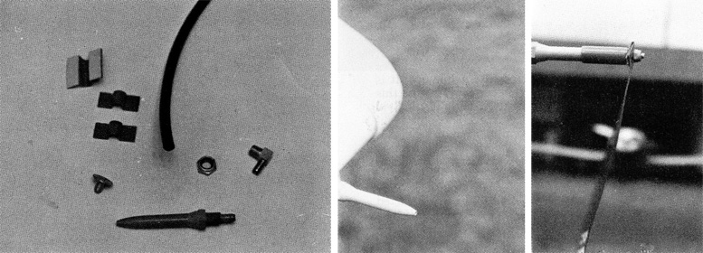
LEFT: Fig. 2 Basic Components.
MIDDLE: Fig. 6 Pitot Tube Installed.
RIGHT: Fig. 7 Pitot Tube cover shown on Pitot Tube.
Adding a second static pressure sensing source on the other side of the fuselage is a good step also but not nearly as important as adding the first static pressure sensing source. If one wants to really fine tune the static pressure sensing location the following procedure can be used.
However, we would like to mention that for the tremendous amount of effort necessary to accomplish this, the added accuracy is probably not worth the effort unless there were a group of identical aircraft and once the most accurate location was found on one airplane it would then be used for all the other aircraft.
The location where static pressure is to be measured is somewhat critical and sometimes difficult to find. A method of finding the proper location is by comparing the static pressure some distance away from the aircraft with the system used in the airplane.
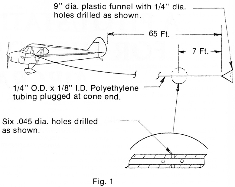
To find the proper location some method of measuring the static pressure away from the aircraft is necessary. One method is called a Trailing Cone Static System, see Figure 1.
Using a trailing cone a homebuilder can obtain an accurate static pressure source. By trying various static locations on the aircraft the homebuilder can locate a static source that is equivalent to the true static pressure. This would then give accurate readings.
Most pitot tubes found on homebuilt aircraft are just aluminum tubes sticking out in the airstream. While adequate, it is far from the best. An aluminum tube normally gives accurate readings at high speeds and low angles of attack.
At low speeds/high angles of attack the aluminum tube pitot head, in effect, stalls out. This gives a pulsating effect on the ram air pressure which, in turn, gives inaccurate readings to the airspeed.
Unfortunately, low speed/high angle of attack is a very undesirable place to have incorrect air speed readings, due to the fact that these low speeds are encountered at low altitudes during landing and takeoffs.
This is not the place to stall an aircraft because the airspeed is reading incorrectly due to the wrong configuration of the pitot head. Pitot tube heads should be designed so that the outside and inside configurations lend themselves to be flown at high angles of attack with a minimum of ram pressure distortion. The location of the pitot tube is also important.
The best location for the pitot tube is far out in front of the aircraft, about one wing chord out in front. While this can be done, the weight and economics of the situation does not normally warrant this drastic a measure. Without sacrificing much accuracy in ram air pressure the pitot tube head can be brought in much closer proximity to the aircraft.
Generally, pitot heads are located just in front of the wing leading edge or just in front and slightly below the wing leading edge. These locations offer a minimal of positional error characteristics. One must remember that no matter where the pitot tube is placed, some positional error will be encountered.
Well, we hope the amateur airplane builder/pilot is saying, that is nice information — but how does this effect me? Well, here comes the commercial. We are proud to announce that Aircraft Development Co. is introducing a pitot tube/static port pneumatic kit.
The kit consists of a pitot tube, static port and enough materials and supplies to connect the airspeed indicator, altimeter, and rate of climb to the pitot tube and static port. For an illustration of the basic components included in this kit, see Fig. 2.
This kit is so simple to install we recommend that those homebuilt aircraft that do not have a professional pneumatic system consider retrofitting their aircraft with this kit. Naturally, we also recommend that anyone now building an airplane consider this kit for their aircraft.
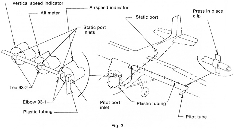
We are so proud of how simple it is to install that we would like to describe its installation to you. Fig. 3 shows a schematic of the location of the components in the airplane. The first step is to screw all the especially designed barbed fittings to the instruments.
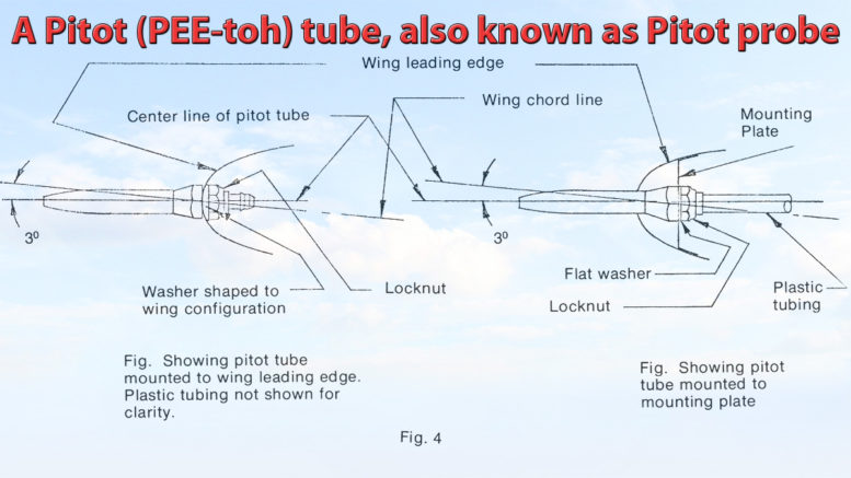
A hole is then drilled in the wing leading edge, or bracket, so that the pitot tube’s aft end can be placed through the hole. If the pitot tube is being mounted to the wing leading edge a washer filed to the shape of the wing’s leading edge is slipped over the aft end pf pitot tube (see Fig. 4) then a locknut is tightened until it clamps the pitot tube assembly to the wing.
That is the hardest part of the job completed. The plastic tubing is slipped over the barbed end of the pitot tube and routed through the wing. At about every foot place an adhesive backed clip over the tube and press in place so that the tube is supported properly. Continue this process until the tubing is brought to the airspeed instrument.
Cut the tube to the proper length with a knife and slip the tube over the barbed elbow on the airspeed. Be certain that once the tube is installed to the barbed fitting it will not have to be removed because once the tubing is installed it is nearly impossible to remove it from the fitting.
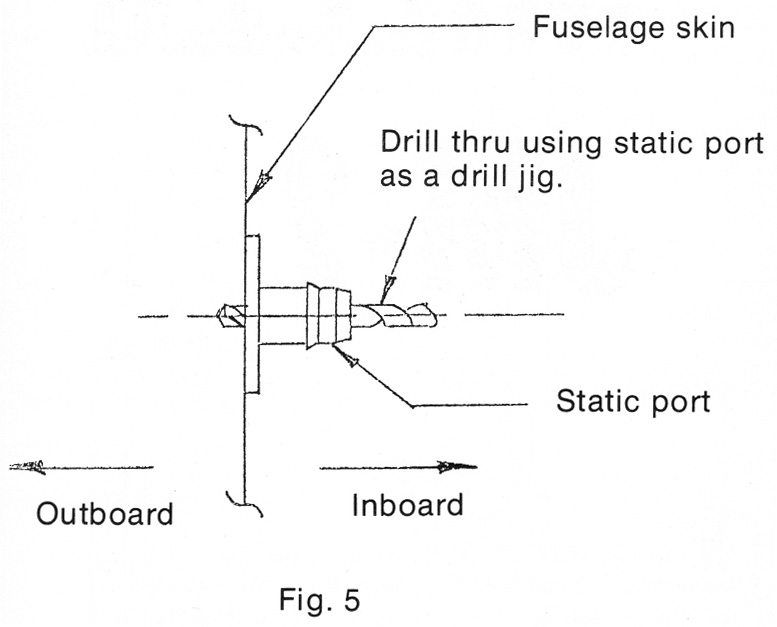
At the selected location press the adhesived backed static port to the inside of the fuselage. Drill a hole through the fuselage using the static port as a drill jig (see Figure 5).
Slip the plastic tubing over the barbed end of the static port and work the plastic tubing to the proper instruments placing the clips as was done with the wing. It will take about 3 or 4 hours of work to install this kit, which will give a very professional, accurate and good looking pneumatic system to your aircraft. One you will be most proud of.
And to cap it off, figuratively and literally, a pitot tube cover can be purchased as optional equipment to protect the pitot tube orifice while the aircraft is on the ground. This pitot tube cover is made of a material that repels insects as do all of Aircraft Dev. Co. pitot tube covers.
This cover will prevent bugs and moisture from clogging the pitot tube and causing erroneous readings. Fig. 6 shows the pitot tube installed and Fig. 7 shows the pitot tube cover on the pitot tube.

Be the first to comment on "A Pitot/Static System For The Homebuilt Aircraft"