

Center Of Gravity
ARTICLE DATE:
Calculations for determining the center of gravity may in fact be conducted by observing the vertical forces originated by the aircraft itself in two positions: horizontal and inclined.
There is a difference of practical nature to be considered here, in view that, in the case of the autogiro, the center of the main wheels was taken as the origin of the coordinates; most helicopters, how ever, are not fitted with wheels.
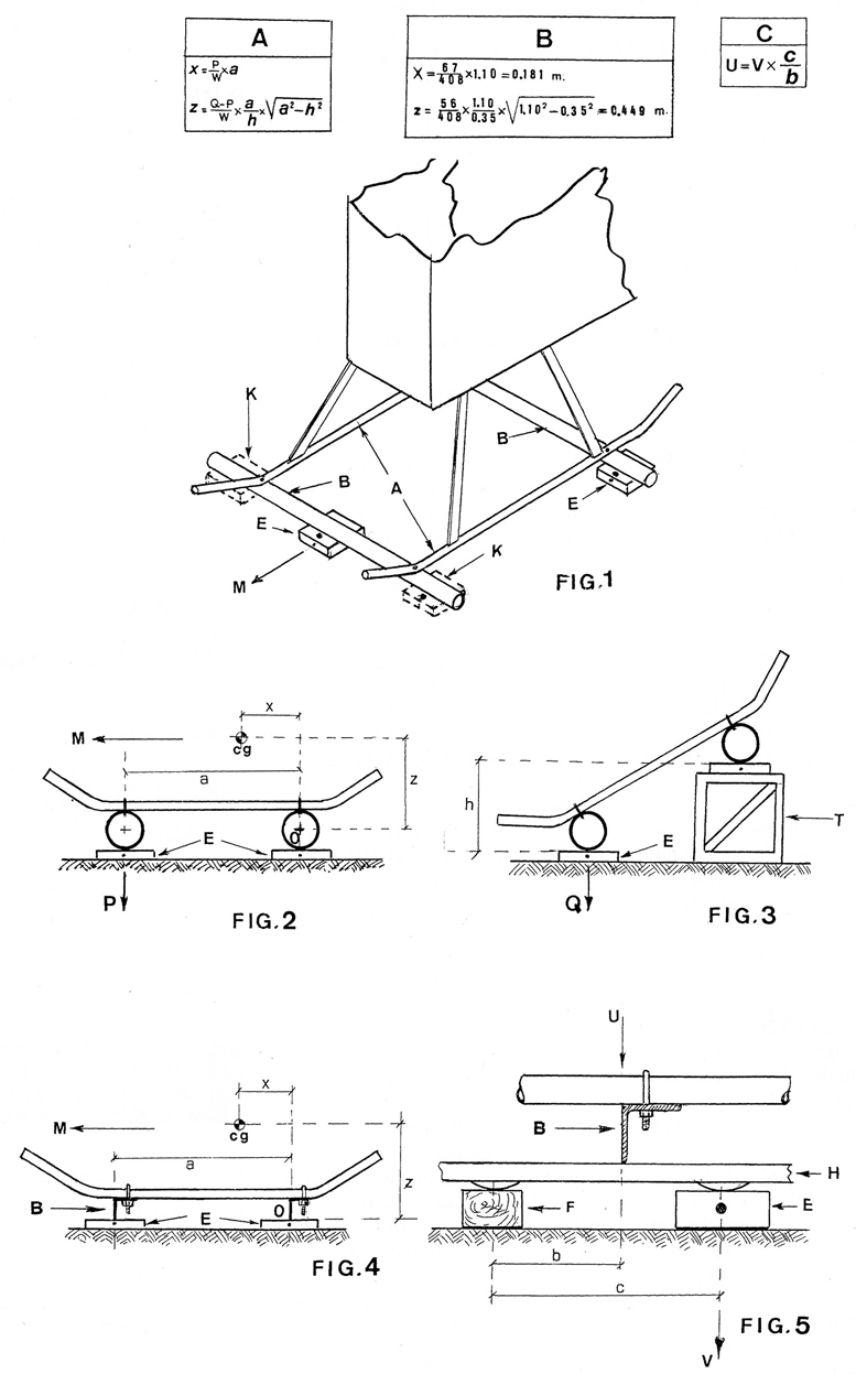
Despite this circumstance, a set of auxiliary parts specifically designed for this purpose may be utilized, as shown in Figure 1. This drawing shows a schematic view of the lower end of a helicopter with skids (A), its advancing direction being shown by the arrow (M).
These auxiliary parts, shown as (B), consist of tubes installed perpendicular to the advancing direction and rigidly attached beneath the helicopter’s skids.
A fundamental requirement is that both tubes have THE SAME EXTERNAL DIAMETER, regardless of their internal diameter, length, weight, etc.. These tubes rest over weighing scales (E), in a manner that the rear tube lies on two scales, whereas the front tube lies only on one.
Two scales (K) are depicted in phantom line for the front part; however, this is merely in the event that the force applied on front scale should exceed the scale’s capacity. The locations of these auxiliary tubes are arbitrary and may be selected by the person performing the operation.
The scales may be of the bath room type used for personal weighing purposes. Figure 2 is a side elevation showing the location of the center of gravity (c.g.) and its coordinates (x) and (z) referred to the CENTER OF THE REAR TUBE, in the advancing direction, as depicted in the drawing. This center is identified by (O).
Thus, with the helicopter in horizontal position, the front tube presses with P force on the corresponding scales (E), plus the weight of the front tube proper. This means that the weight of the tube must be subtracted from the weight reflected by the scale in order to find the value defined by P.
If either the P or the Q values exceed the capacity of the corresponding scale, two scales may be used, as shown in (K), Figure 1. In this case, the correct value is the sum of the weights of both scales (K). The system described in the last paragraphs of this article may also be used.
Figure 2 also reflects the distance between both auxiliary tube axes, shown as: (a). This being a value required for determining the center of gravity. Once this is accomplished, a second operation is called for using a similar criterion although with the rear tube raised in (h) magnitude in respect to the front tube, as indicated schematically in Figure 3.
Also in this position, the same scale must withstand the pressure of the helicopter itself, plus the weight of the front tube, so that the weight of the latter should be subtracted and we thus obtain a new force identified by (Q).
In said Figure 3, a frame or stool (T) is shown for supporting the scales and the rear tube, so that the rear tube is positioned higher than the front tube. The two lengths (a) and (h) shown in Figures 2 and 3 and the forces applied on the front scales are therefore established, with the helicopter in both horizontal (P) and in slanting (Q) position.
A further value is lacking, namely the weight of the helicopter, identified by (W), evidently the sum of all the scale readings after subtracting the weight of all the auxiliary tubes and fittings.
The formulas used for deter mining a helicopter’s center of gravity coordinates are contained in box A, and it should be noted that the resulting dimensions refer to the CENTER OF THE REAR TUBE.
Despite the fact that the use of these formulas is very simple, an example is described hereunder using imaginary data which could nonetheless apply to an actual case.
The sum of all the scale (E) readings reveals a value of 420 kg. The weight of the front auxiliary tube is 5 kg, and the weigh of the rear auxiliary tube is 7 kg. Their total weight is 12 kg.
Thus, the total weight (W) of the helicopter is;
W = 420 – 12 = 408 kg
With the helicopter in horizontal position, the front scale (E) provides a reading of 72 kg. However, since the weight of the front tube is 5 kg, the resulting value of P is:
P = 72 – 5 = 67 kg
The same scale, with the helicopter in slanting position, provides a force reading of 128 kg. By subtracting the same 5 kg from this value the resulting Q force is:
Q = 128 – 5 = 123 kg
The difference between both forces is:
Q – P = 123 – 67 = 56 kg
Concerning the length dimensions, the distance between the centers of the auxiliary tubes, defined as (a), is 1.10 m, and the height (h) between the centers of the auxiliary tubes is 0.35 m. This height is the same as the distance between the lower edges of both tubes.(see again fig3.)
The development of the calculation becomes clear in box B, resulting in that the center of gravity is located in the following coordinates IN RESPECT TO THE CENTER OF THE REAR AUXILIARY TUBE:
x = .181 m
z = .449 m
Instead of using tubes for the auxiliary elements (B), it may possibly be more practical to use some other laminate shape, or even wood. Figures 4 and 5 show angular profiles, which are easier to adhere to the helicopter skid tubes by means of U-shaped adapters fitted with threaded ends and nuts.
In either case, the above indications apply, and it should be under lined that BOTH AUXILIARY PARTS MUST HAVE THE SAME PROFILE OR THE SAME HEIGHT, and also that the coordinate origin (O) is located, as shown in Figure 4, ON THE LOWER EDGE OF THE AUXILIARY ANGLE OR PART resting on the scales.
Despite the fact that the proposed objective is fully achieved, it must be borne in mind that, should the weight applied on a scale (E) exceed the scale’s maximum allow able weight, an auxiliary part (H) may be used, as shown in Figure 5.
This part (H), which with stands the weight of the helicopter in its central position, is distributed between a fixed resting point (F) and the scale (E). The force (U) of the helicopter proper is derived from the formula indicated in box C based on the scale reading (V) and the distance between the supporting points shown in figure 5.
HELICRAFT
FROM “The Helicopter Experimenter” printed about 1957 Thanks to Richard Pankratz
The best method for the amateur builder to follow in designing a helicopter would probably be the proportion system. This is roughly scaling down several proven helicopters to fit the designer’s aim. By listing a number of helicopters’ specifications, such as gross weights, rotor disc areas, and engine horsepowers, he will arrive at a list that looks something like this:
Approximately 12 1/2 lbs. gross weight per horsepower.
Approximately 4 1/2 sq. feet of rotor disc per horsepower.
Approximately 2 1/2 lbs. per sq. foot of rotor disc.
By applying the information from such a list to a proposed design, the homebuilder may then proceed with confidence knowing that, design wise, at least, he will have enough power for weight, etc. Because one-man helicopters are likely to prove the most popular with homebuilders, a one-man design will be used as an example.
There are two-cycle, target drone engines of 35 h.p. that weigh approximately 40 lbs., and auxiliary engines for gliders that develop 40 h.p. with a weight of 50 lbs. Outboard motors of comparable h.p. weigh more due to their water cooling systems. An average small 2 cycle engine might be assumed to develop 50 h.p. with a weight of 100 lbs.
The average weight of a pilot and parachute may be figured at about 200 lbs. Allowing 200 lbs. for fuselage, landing gear, driving mechanism, main rotor and tail rotor, etc., the total machine and, pilot would gross in the neighborhood of 500 lbs.
This would be within the design criteria, of a 50 h.p. helicopter, and good performance could be expected, providing, of course that extreme care is taken in the construction, particularly, of the rotor to assure a high degree of efficiency and of the driving mechanism to operate with a minimum loss of power.
A helicopter using propulsion units at the rotor tips for power, thereby eliminating the need for a transmission, anti torque rotor, cooling fan, etc. could be made much lighter. Large fuel consumption, short range, and the necessity of a huge fuel tank partly offsets the simplicity of the jet ‘copter.
Propulsion tipped helicopters have been built weighing less than 100 lbs, less pilot and fuel. In jet ‘copters, power is measured in lbs. of thrust, one lb of thrust being roughly equal to one h.p., depending on tip speed.

Single main rotor for lift, tail rotor counter acts torque and gives directional control. – Relatively simple.
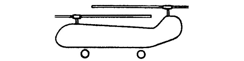
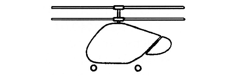
Tandem rotors turning in opposite directions cancel out torque. – Successfully applied to large machines.
Inter-meshing blades turn in opposite directions to cancel torque. – Relatively complicated transmission.
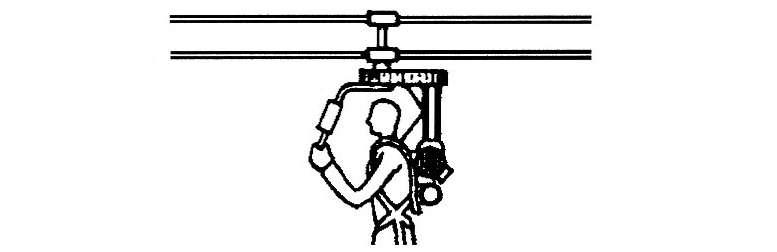
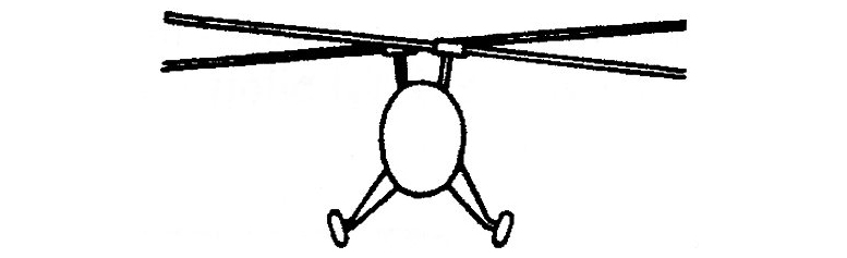
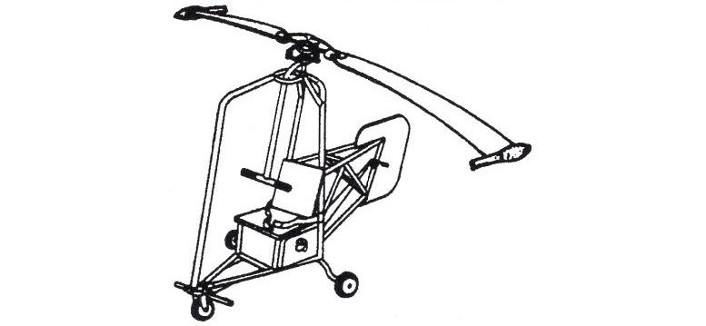
Strap-on-coaxial. Very light, sacrifices comfort. Pilot’s feet landing gear. – Better suited for military.
Coaxial rotors turning in opposite directions cancel torque. – Relatively complex mast and rotor head gearing.
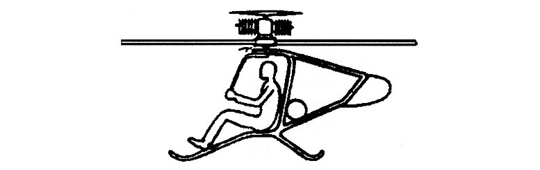
Torque reactioncoaxial. Engine mounted on main rotor. – Requires relatively more powertoweight ratio.
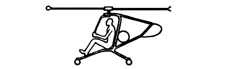
Jet, rocket, compressed air at rotor tips. – No torque light and simple but has short range due to high fuel use.
The Helicraft Jet Rotor-tip jet powered; empty weight 180 lbs; Payload;, up to 420 lbs., maximum speed: about 80 m.p.h.; engine thrust 20 to 40 lbs. each; fuel: kerosene, alcohol, propane, etc.; type of engines usable: ramjet, pulsejet, turbojet, pressurejet.
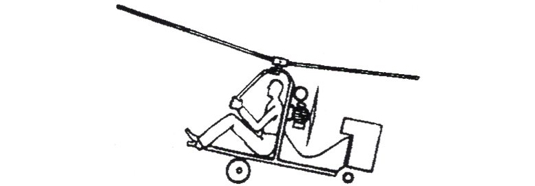
Autorotator. Powered for thrust. Not a true helicopter needs wind to “hover”. Rotor turns freely. Autogiro type, rotary gliders.

Be the first to comment on "Determination Of The Center Of Gravity In Helicopters"