

Belgian M80 Masquito Helicopter Development
Helicopter Design Process
Why aren’t there more helicopters?
The M80 Masquito Helicopter: ….Unlike the traditional airplane, the helicopter requires demanding attention. Maintenance, constant inspections and adjustments insidiously plague the economic factor. It appears that the helicopter, in its present state of complexity and economics, will not encourage widespread acceptance as in the case of the airplane.
The past decade of helicopter development points to a continuous trend toward highly complex design… a trend of over-designing and over-emphasizing to meet basic requirements. My personal suggestion to the helicopter designer of today is to reappraise and reverse this trend with concentrated efforts toward simplicity in design.
Optimum performance, reliability and maintenance costs are the three outstanding areas that are critical to the future of the helicopter. This may invite criticism, but the crux of the matter lies in the fact that today’s complex design standards and the exorbitant cost of flight instruction and ownership are the main deterrent factors restricting the growth of the helicopter….
Excerpt from the Foreword of “Helicopter Design and Data Manual” by Stanley J. Dzik – 1984.
The Design paradox
Although this was written 16 years ago the author’s suggestions have not been implemented up until now. Masquito Aircraft has directed every effort to design and manufacture a 2 seat helicopter that will be simple to operate and maintain – the “M80 Masquito Helicopter”. This goal sounds logical and simple, but the design and engineering involved to obtain a simple result is extremely complicated – a design paradox.
In his book Military Helicopter Design Technology, Raymond Prouty says the following:
The design of any vehicle is an exercise in compromise, but this is probably more true in the case of a helicopter than of any other vehicle. In almost every decision, the designer must keep in mind that what is good for hover performance is bad for forward flight and what is good for forward flight is bad for hover.
In no other vehicle will the relationship between empty weight and payload be so uncompromisingly one-to-one. In addition, the maximum speed limit of a “pure” helicopter is apparently even more rigorously enforced by basic physical principles than was the “sound barrier” that airplanes once faced. For these reasons, the helicopter designer cannot be said to be seeking the optimum design, but the “least worse compromise”.
[…] An extra pound or kilogram of empty weight on an airplane usually results in nothing more serious than a small increase in the take-off distance. An extra pound or kilogram of empty weight on a helicopter, however, results in something very serious – a reduction in allowable pay load. For this reason, the helicopter designer must take advantage of all possible weight saving methods while also never losing sight of his responsibility in the fields of safety, cost, reliability, maintainability, and crash worthiness.
Design of the M80 Helicopter
In the design of the M80 we have adhered to the above goals of both authors as much as possible, and using these criteria some noteworthy design results are:

The titanium tubes must be precisely cut to ensure that they make a perfect fit when joined. For maximum strength, welding material and heat input must be kept to a minimum.
The M80 Masquito Helicopter is constructed by using classic aeronautical methods, but combinations of chrome molybdenum steel, titanium 3AI-2,5V tubing, titanium 6AI-4V sheet and billet, high grade aluminium and carbon composites have been employed to reduce the weight of the M80 to the lowest, affordable configuration possible. We have spent considerable time and effort training ourselves in the correct techniques for welding titanium.
We spent several weeks performing welding operations on representative sample pieces and tested the results using destructive techniques. We now have in-house TIG welding expertise in titanium welding, certified by a European control organism.
“Ti 3AI 2,5V alloy was created for use as seamless tubing in high pressure aerospace hydraulic lines. Ti-3-2,5 tubing offers high strength, light weight, good cold formability, good fatigue resistance, excellent corrosion resistance, good torsional properties and a natural dampening characteristic”.
“Ti-3-2,5 tubing does not have a high specific elastic stiffness compared to steel or aluminum alloys, but this can be an advantage since the low modulus gives the material a natural dampening effect. A Ti-3-2,5 frame will also be durable, resistant to fatigue and immune to all corrosion problems which would plague steel and aluminium frames”.
“While the Ti-3-2,5 tubing never needs to be painted for corrosion purposes, it can be anodized, polished, etched, bead blasted or epoxy coated into a wide variety of attractive finishes.”
The above is an extract from “Ti-3AL-2,5V Seamless Tubing Engineering Guide”, Third Edition – SANDVIK

A jig holds the M80 Masquito helicopter tubes in the correct position while all the pieces are being joined.
Our 2nd M80 Masquito Helicopter prototype was too heavy. To provide future users with an acceptable useful pay load we needed to decrease the empty weight of the final production version significantly. In spite of our former conviction that an acceptable empty weight could be achieved using Cr-Mo steel we have not been able to achieve this goal and had to use Titanium alloys and carbon composites instead of steel and aluminium where ever practical.
The Ti-3-2,5 tubing we now use to build our 3rd. M80 prototype is exactly the same as is used on various Airbus and Boeing aircraft and is sourced from an Airbus supplier. A Titanium frame for the M80 is nearly 40% lighter than the original one made of Cr-Mo steel. Other high grade steel components used in the main drive assemblies and rotor head were replaced by Ti-6AI-4V plate and sheet material when possible.
Our choice of Titanium alloys and carbon composites for the structure is much more expensive than the Cr-Mo steel used in the frame and drive system, and the aluminium tube used for the tail boom we had formerly used, but this was the cost of increasing the useable payload to give good performance.
The second M80 Masquito Helicopter design of landing gear supports fabricated using glass fibers has been re-calculated and these are now manufactured using unidirectional carbon fibers instead. The end result is a thinner vertical section and reduced weight, with only a slight decrease in maximum allowable vertical decent speed for ground contact.

Titanium tubes are pre-cut and inserted into a
welding jig.
We have chosen a normal tail rotor configuration and not a shrouded tail rotor. A fenestron is often associated with annoying high pitched noise and although this design implies smaller fan diameters for the same thrust/power ratio, a shrouded tail rotor or “fenestron” design is heavier and has higher drag in forward flight.
All power saved by using a particular anti-torque configuration means this amount becomes available for the main rotor. As with a conventional tail rotor, the larger the diameter of the fenestron, the less power required to generate the needed thrust. We feel that the classic configuration is the most plausible in terms of efficiency and economy for our M80 Masquito Helicopter.
We have not used a “Notar” (NO TAil Rotor) design because it would also require a much larger power requirement than our classic tail rotor configuration and this would decrease the hover and climb performance of the M80. The Notar design needs a much larger tail boom section. This results in a significant weight penalty because most of the tail boom weight is far behind the C.G., so a much larger compensating weight would have to be moved to the front of the helicopter. This solution would considerably decrease the allowable payload.
Operational weight
Disadvantages in increasing the operational weight are:
-
Fuel tanks must be enlarged to accommodate the additional fuel required for the same range, or decreased range with the same fuel capacity.
-
Landing gear must be strengthened to maintain the design touchdown rate of descent at the higher weight.
-
Rotor control system must be strengthened.
-
Body structure must be strengthened to maintain the design load factor.
-
Drive system must be strengthened because of increased power required.
-
Hub and blades must be modified because of higher loads.
-
Horizontal tail size must be increased to maintain acceptable stability level.
-
Weight of engines if up rated.
-
Tail boom weight increases if the main rotor radius is increased.
(cfr. “Rotory-Wing Aerodynamics” – W.Z.Stepniewski C.N.Keys)
M80 Masquito Helicopter Engine power and payload
A more powerful engine does not automatically mean increased payload!
The trade-off between desirable characteristics is radical in helicopter design. There are essentially 2 ways of increasing load capacity:
-
Lower the empty weight of the helicopter.
-
Increase the installed power.
An extra unit of weight on the helicopter means a unit less of payload. Our 2nd M80 pre-production prototype was too heavy and the corresponding O.G.E. hover ceiling was probably only 2.000 ft on a standard day at maximum take-off weight which still meant in our case, 3,5 hours of flight. We looked for ways to reduce the empty weight significantly to increase the payload and/or hover ceiling.
We substituted all ChromeMoly steel in the frame with Titanium alloy; this means nearly a 40% weight reduction in the frame alone. Other weight savings – without endangering structural integrity – were possible using carbon composites. Decreasing the empty weight is by far the most effective way of increasing the payload and/or hover ceiling.
Installing a more powerful engine usually has many drawbacks. In a fixed wing aircraft a larger and heavier engine usually means making adjustments to keep the C.G. in the correct place and this change is usually not very complicated because the aircraft was often designed with more than one engine in mind. In the case of helicopters, the design usually starts with one available engine and worked from there onwards. When we chose the Jabiru, they only had the four cylinder 2200 engine, the six cylinder 3300 engine only came two years later.
A more powerful engine usually means extra weight, and higher forces originating from the engine that are carried over to the load-bearing frame and drive components. A more powerful engine will consume more fuel, so if you want to conserve your flying time, extra fuel will have to be carried. The extra power will almost certainly mean extra strength requirements in most of the load bearing structure, rotors and drive system. The sad fact of the matter is that a lot of the additional power produced by the six cylinder would be used to lift the extra structural and additional engine weight caused by the increased installed power, and not be available for increased payload!

The design of the load bearing structure was drawn on paper, but our_drawings have since been put into digital format by Russel Pescod using our solid modeling software.
We had been forced to make modifications to the standard Jabiru 2200 engine to make it suitable for our M80 Masquito Helicopter requirements. In the second half of 2000 and the first months of 2001, we began to make important modifications to improve overall engine performance. We needed to adapt the engine so that an electronic rpm governor could be more easily installed. Preliminary tests using a mechanical governor did not produce totally satisfactory results in combination with the standard carburetor.
Later, when tests with a dual carburetor configuration were performed, the mechanical governor solution became further complicated. We eventually decided to eliminate the carburetor in favour of an electronically controlled fuel injection and variable timing ignition system. Full details of these changes can be found on the Jabiru modified engine page.
Choice of load-bearing structure
Once the design choice using thin walled tubes was selected, the designer added redundancy to it by making triangulations. Having a redundant load bearing structure means that if any tube cracks or fails completely, the integrity of the complete structure is not endangered. When this method is correctly applied, the load carried by the failed tube is safely taken over by its’ neighbours. The following is a hand drawn perspective of the load bearing structure.

When the frame configuration was finalised, estimates were made to determine the nominal loading of each tube and connecting points by distributing the maximum take-off weight over all the load bearing components in a realistic manner.

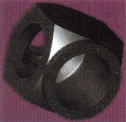
A VX generated image of the M80 Masquito helicopter rotor head component.
The VX program would have allowed us to apply finite element analysis to approximately determine the stresses in all parts of the M80 Masquito Helicopter frame and critical components before ground and flight tests much more easily than the route we had to follow before. These results will later be compared to real stress data recorded from strain gauges during actual flight maneuvers.
Other additional factors must be introduced in these calculations. The estimates of the nominal loading must be increased by and superimposed on in-flight loads, cyclic loads, torque loads, limit loads and finally by the required safety factor. Changing the dimension or position of any member can have a significant effect on all its’ neighbours and can not be done without serious thought and consideration.
VX generated image of the M80 helicopter tail rotor gear box housing.
There are many individual calculations involved and although they are not very complicated, each has to be recalculated every time a piece or its’ position is changed. A computer is an ideal partner when this type of repetitive “what if” calculations need to be done. Once the critical work of introducing the 3D model of the load bearing frame in the computer program has been completed and manually checking some of the results, we can use the program to calculate the loads on each piece, and in varying circumstances.
When the resultant answers are combined with color rendering in the reproduction and we introduce threshold values, critical areas become highly visible. In our diagrams, blue shades are compression stress, red shades are traction stress and green are neutral values.
The following diagram shows the compression stress (dark blue color) of certain sections of the tail boom. The weight of the engine support pushing down on the tail boom close to the root (on the left), and the compression stress of the tail boom being forced against the left side supporting tail boom strut by the tail rotor are clearly visible.
In the image, the bright red rectangle is the traction stress caused by the connecting fixture of the strut to the tail boom. Remember that our main rotor turns clockwise when viewed from above, so that our tail rotor is placed on the right hand side of the tail boom and pushes the tail boom to the left to counteract the torque of the engine driven rotor.

Solid Works Masquito M80 helicopter rotor head – After each component has been modeled, they can be built into an assembly.
The next representation shows a red color on the right front side of the M80 Masquito Helicopter tail boom and depicts the traction stress in that section of the tail boom. The tail boom is fixed at the root (connected to the cabin back wall structure) and fixed again by the ends of the tail boom supporting struts which are connected by hinged fixtures at both ends to avoid additional bending stresses.
The 3 strut configuration is also redundant, meaning that any one of the struts could fail and that the remaining 2 can safely carry the limit loads as required by the VLH requirements. A fatal accident in the UK in early 2000 involving a Hughes 300 was caused by one of the only two tail boom supports failing in flight, (incorrectly performed welding fix) which then allowed the tail boom to be pushed by the force of the tail rotor up into the main rotor, with tragic results.

Helicopter tail boom stress analysis
In normal circumstance the tail rotor pushes the end of the tail boom to the left causing the front section of the tail boom to bend to the right. We can now “see” that the outer wall of the foremost section of the tail boom is being stretched by the boom being bent to the right. The colors change as the simulated loads are varied. When the helicopter is on the ground and not under power, the blue compression loads on the top of the tail boom caused by the engine weight remain, but most of the other areas “become green”.
When we ran the program on the final design we noticed one piece did not meet the UK CAA’s requirement. The bottom supporting strut for the tail boom was slightly under dimensioned. What do we mean by under dimensioned ? The program showed that when the normal flight loads under maximum take-off weight were increased by the required limit load of +3.5 (which are impossible to reach in the M80 because the rotor blade area is not large enough) AND this limit load is multiplied by a safety factor of 1.5, the bottom supporting strut would buckle under the compression load.

Helicopter airframe stress analysis
To correct this “problem” we had to slightly increase the diameter of the bottom strut, so this was done. For esthetical and practical reasons, we also increased both horizontal struts on either side of the tail boom to the same diameter although this was not at all necessary. If we hadn’t, we needed two different sized tubes and two correspondingly different diameter attachment pieces for the construction of the struts, effectively doubling the number of different pieces.
PLEASE NOTE: Masquito Aircraft are no longer in existence and the Masquito kit helicopters are no longer produced. The company was eventually dissolved with some of the staff pursuing a new aircraft engine manufacturing project (ULPower) with no relation to the original Masquito Aircraft company or helicopter. All property is copyright protected.


Be the first to comment on "M80 Masquito Helicopter Development"