
University Helicopter Designs
ARTICLE DATE: Unknown
34th Annual AHS International Student Design Competition Undergraduate Category
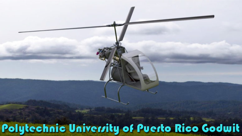
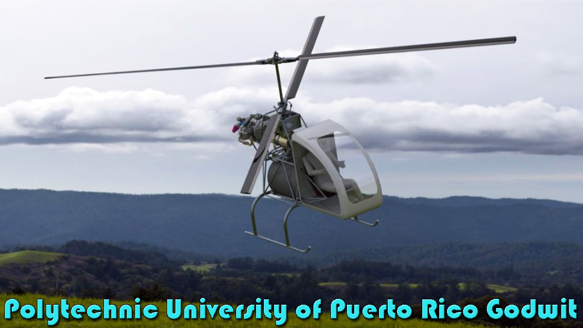
COURTESY: Polytechnic University of Puerto Rico Godwit Coaxial Helicopter
1. Mission Requirements
Vehicle requirements were split into those explicitly stated by AHS international in their Request for Proposals and those created by our team so that our vehicle would be able to complete the mission stated by AHS International satisfactorily.
See Table 1.
Table 1:Mission Requirements
| Requirement | Target |
| AHS Requirements | |
| Aircraft shall fly autonomously or receive commands from a Ground Controller | R/C controlled and optionally autonomous |
| Payload shall simulate a human occupant | 176.4lb (80 Kg.) and the volume necessary for a human pilot |
| Development and testing viability within the next 3-5 years | High technological maturity levels |
| Aircraft shall be unoccupied | 0 crew members |
| VTOL Capable | VTOL |
| Minimum Range | 1.62 nm |
| High endurance | 24 hours hovering |
| Team Requirements | |
| Flight time before overhauls | 1000 hrs |
| Autorotative index | 24 |
| Control system redundancy | Triple redundant |
| High engine cooling rate | In rotor downwash |
| Structural Integrity | Capable of handling a 4g landing |
| Transmission efficiency | Above 95% |
2. Pre-Layout Selection Preliminary Sizing
To arrive at a pre-layout selection sizing, brake horsepower specific fuel consumption and weight empty fraction values from historical data was used. By deriving our own sizing equation, the team arrived at preliminary vehicle weights at different disk loadings.
Table 2: Pre-Layout Sizing
3. Concept Selection Trade Studies
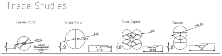
Figure 1: Concept Selection Trade Studies
Based on pre-layout selection preliminary sizing results, four vehicle configurations were evaluated and drawn using AutoCAD. A coaxial configuration was selected since it allowed for a practical rotor footprint at low disk loadings (using total coaxial disk area). The principal setback of this configuration was low figure of merit due to rotor wake interference.
This effect was worsened by the low disk loading in which the vehicle was designed to operate, since figure of merit tends to decrease with disk loading. However, it was decided that low disk loading at a feasible rotor radius outweighed the negative impact of a lower than usual figure of merit.
4. Post-Layout Selection Preliminary Sizing
A more detailed sizing of the vehicle that took into consideration a coaxial arrangement was performed after vehicle layout selection. The goal was to use modified momentum with corrections for a coaxial configuration to arrive at the design goals derived from our first iteration.
Results showed that the effects of a lower figure of merit could be reduced by increasing total disk area in a coaxial configuration. Final preliminary sizing is shown below.
Table 3:Post Layout-Selection Sizing
| Disk Loading (lb./ft.²) | Gross Weight (lb.) | Empty Weight (lb.) | Power (hp.) | Disk Area (ft.²) | Diameter (ft.) |
| 0.90 | 822 | 395 | 39 | 905 | 12 |
Final Iteration: The Godwit
5. Vehicle Drawings & Schematics
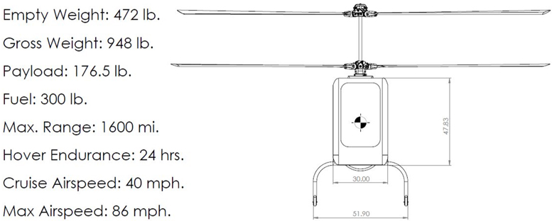
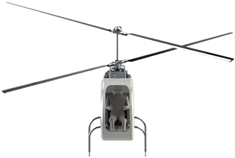
Figure 2: Front View
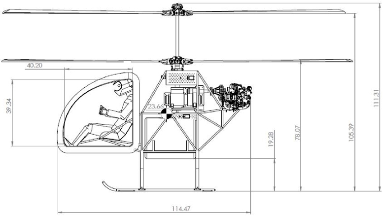
Figure 3: Side View
6. Vehicle Drawings & Schematics
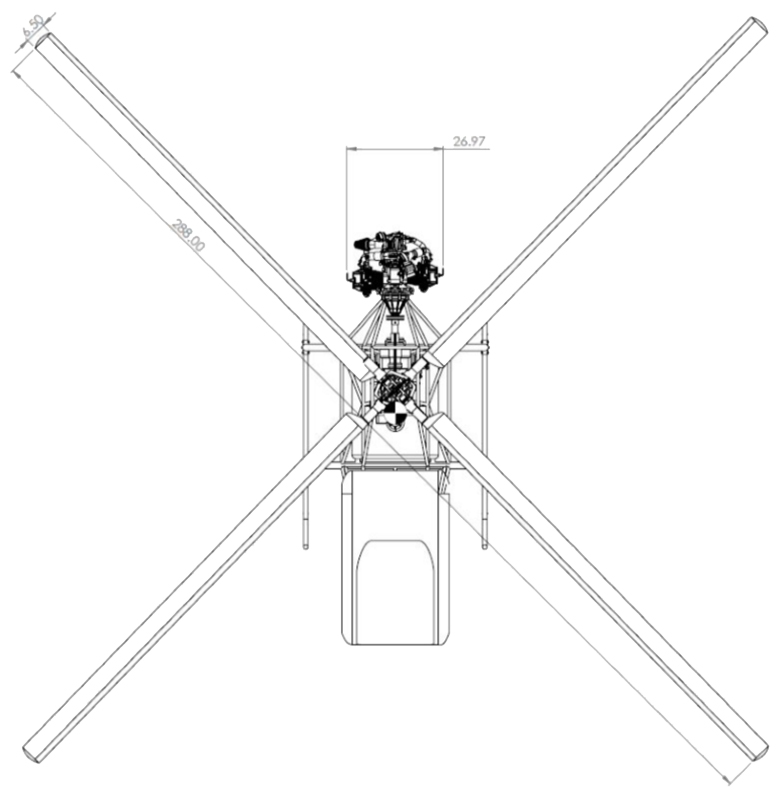
Figure 4: Top View
7. Coaxial Rotor Performance & Dimensions
The Godwits rotor blades are characterized by large amounts of twist and a Boeing Vertol VR7 airfoil cross section. The coaxial rotors that are used operate at very low disk loadings, which greatly reduces power required for the blades.
Detailed rotor performance was obtained using a modified form of Vortex Theory that was derived for this competition. The latter considers the induced velocities that affect the upper and lower rotors of a coaxial configuration.
Results were validated with an empirical equation derived by Stepniewski for coaxial rotors. Blade Geometry is presented in figure 5. Figures 6 to 11 show Vortex Theory Results.

Figure 5: Blade Front and Side Views
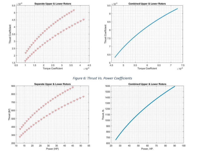
Figure 7: Thrust Vs Power, lb. & hp
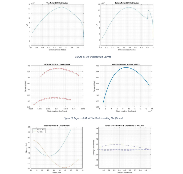
Figure 8: Lift Distribution Curves
Figure 10: Moment Vs Power, lb.ft. & hp
Figure 11: Rotor Airfoil
8. Forward Flight Performance
Parasite, profile, and induce power curves were calculated at different airspeeds for the Godwit coaxial helicopter. Estimates on cruise speed, maximum airspeed, maximum dash airspeed, and maximum range were generated with the plots. See figures 12 and 13.
The Godwits helicopter endurance performance at hover is very high to comply with RFP requirements. Maximum range is also very high at approximately 1600 mi. Cruise and maximum airspeeds are 40 mph and 86 mph respectively.
These low cruise and maximum airspeed values are a consequence of selecting a very light and low horsepower engine that cannot overcome parasite drag buildup as airspeed increases. However, the selection of this engine was deemed necessary by the team to comply with endurance requirements.
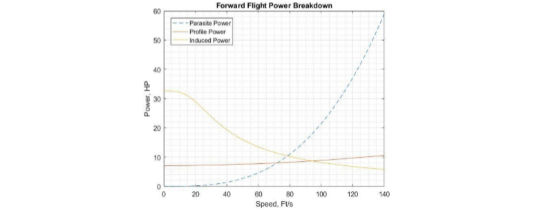
Figure 12:Induced, Profile, and Parasite Power Breakdown
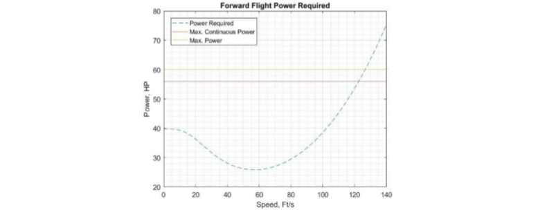
Figure 13: Total Power Required Vs Airspeed, hp & ft./s
9. Autorotative Performance
The Godwit has an autorotative index of 37, which is exceptional considering that values above 20 are considered good for single engine helicopters. Additionally, altitude drop and descent velocity increase was calculated for the first 4 seconds of an engine out condition.
The curves generated with this autorotation analysis are illustrated in the graphs below. They show that the Godwit has exceptional autorotative qualities that would allow an autopilot to safely land the vehicle in emergency condition.
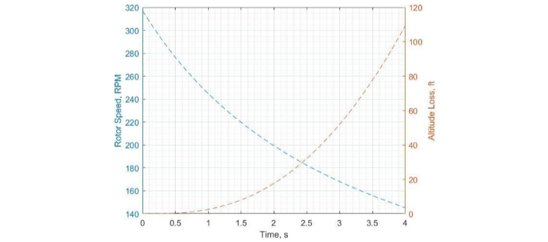
Figure 14:Rotor Speed and Altitude Loss Vs Time, RPM, ft. & s
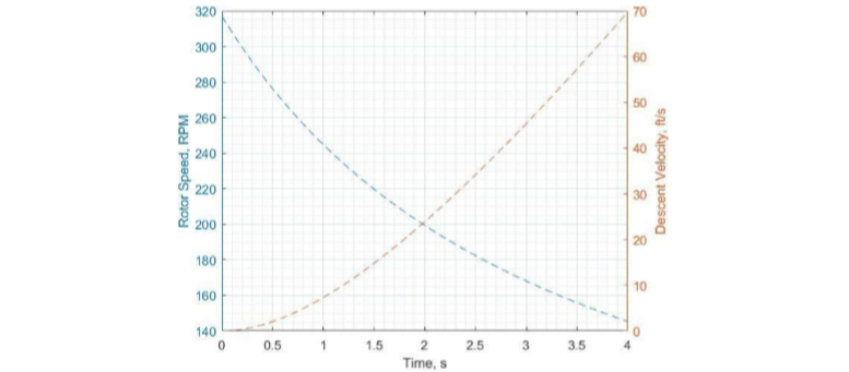
Figure 15: Rotor Speed and Descent Velocity Vs Time, RPM, ft./s. & s
10.Vehicle Subsystems
Teetering Hub A teetering hub with coning hinges correlated best with mission requirements. This configuration is frequently used for ultra-light two bladed helicopters due its simplicity, low weight, small profile, and maintainability.
The configuration also takes some of the bending loads that rotor blades would otherwise take and allows them to be lighter than they would have been otherwise. Controllability is achieved with an upper collective pitch mechanism (no cyclic), and a lower cyclic and collective pitch mechanism.
By eliminating the entire swash and control assembly from the upper rotor, the configuration delivers very low wetted area and provides significant weight savings.
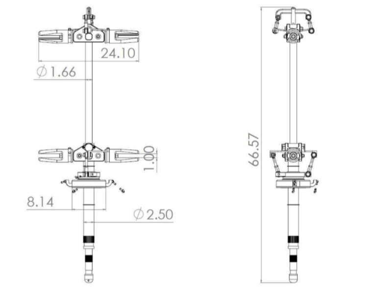
Figure 16: Main Mast and Hub Front and Side Views
11.Vehicle Subsystems
Transmission & Clutch Main requirements for our transmission design were high efficiency and the reduction of vibrations. High efficiency is necessary to ensure that only negligible amounts of power will be lost as our drivetrain delivers torque at the appropriate RPMs to our coaxial rotors.
Vibration reduction is important because it increases the life of mechanical components, provides passenger commodity, and makes for a safer and better designed vehicle. To achieve these goals, a two shaft transmission employing both spiral bevel and helical gears was employed.
A total of 5 meshes were are used, leading to an estimate an overall transmission efficiency of 94%. Final design can be seen in figure 8. The transmission is fitted with a sprag clutch allow autorotation during an engine out condition. The clutch does this by splitting our drive train in two sections.
In this way, the section connected to our engine shaft can cease movement but the drivetrain that extends from our clutch to our rotors can continue rotation due to blade inertia. See sprag clutch in figure 18.

Figure 17: Sprag Clutch
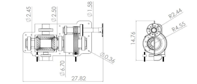
Figure 18: Spiral Bevel and Helical Gear Transmission
12.Vehicle Subsystems
HKS 700E Engine The godwit uses an HKS 700E 4 stroke engine for its propulsion system. From manufacturer data, we can estimate the engine to operate at a BSFC close to 0.42 lb./hp.*hr. Using waste heat recovery systems, we can easily lower this number by 10 percent (Jadhao 2013).
We will take 0.378 lb./hp.*hr. as our engine BSFC and assume that the heat recovery system would be developed and integrated to the engine by the manufacturer. As manufactured, a power to weight fraction of 0.48 hp./lb is provided by this engine model. BSFC and Power to weight are both very good considering the performance penalties that lower power engines suffer.
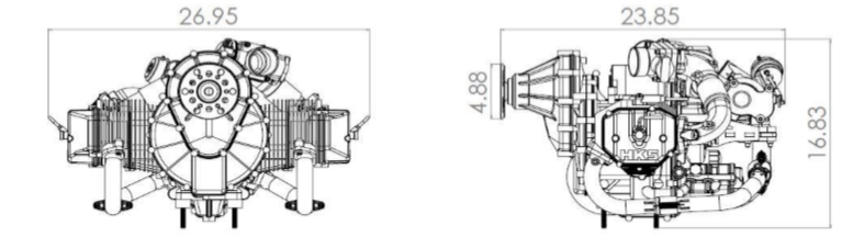
Figure 19: HKS 700E Engine Dimensions
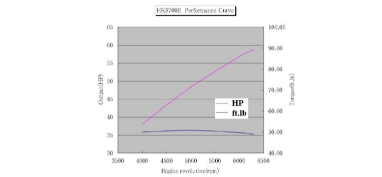
Figure 20: Output Power and Torque Vs Engine Revolutions, hp, ft.lb. & RPMs
13.Vehicle Subsystems: Frame & Skids
It was decided, early in the design process, that all vehicle systems would strive to achieve the lowest weight they could. Hence, the truss structure that supports the Godwit is the product of an aggressive approach to weight savings.
Trusses were drawn in such a way that they wrap around all major helicopter systems. The team made sure that no members took bending, and that particularly heavy systems have many truss nodes at their frame attachments to distribute loading.
Because of this, very lightweight small diameter tubes could be used. Panels were created to hold all electronic systems, and have boring to further decrease frame weight. The total weight of the frame, skids, and electronics panels is 60 lb.
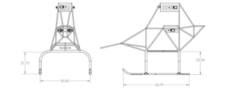
Figure 21: Frame & Landing Gear Front and Side Views
Structural integrity was verified by submitting the frame to a finite element analysis static test using Solidworks. This evaluation was done at a vehicle gross weight of 948 lb.
The weight of each component was added as load at its attachment point to our frame and then multiplied times 4 to simulate a 4g loading condition. Results showed that our 60 lb. frame could in fact tolerate a 4g loading. See figure 23.
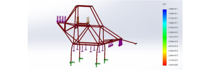
Figure 22: FEA 4g Loading Simulation-FOS Plot
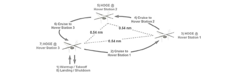
14.Segment by Segment Mission Analysis
The table below provides a segment by segment mission profile description. All values were calculated at average mission segment gross weight using rotor figure of merit and transmission efficiency coupled with momentum theory and endurance relations.
These values prove that the Godwit can in fact complete the mission proposed by the RFP with 5 gallons of gasoline remaining in its fuel tank.
| Mission Segment: | Takeoff | Cruise | HOGE | Cruise | HOGE | Cruise | HOGE | Landing |
|---|---|---|---|---|---|---|---|---|
| Pressure altitude (ft.): | 0 | 50 | 50 | 50 | 50 | 50 | 50 | 0 |
| Ambient air temperature (R): | 946.65 | 946.48 | 830.83 | 830.69 | 734.16 | 734.5 | 653.82 | 653.05 |
| GW Start (lb): | 0 | 52.14 | 0 | 52.14 | 0 | 52.14 | 0 | 0 |
| GW End (lb.): | 0 | 0.54 | 0 | 0.54 | 0 | 0.54 | 0 | N/A |
| Airspeed (nm/hr): | 5 | 0.62 | 480 | 0.62 | 480 | 0.62 | 480 | 5 |
| Distance (nm.): | 5 | 16.22 | 14.57 | 13.33 | 12.07 | 11.08 | 10.09 | 9.30 |
| Time (min.) | 16.25 | 16.22 | 14.57 | 13.33 | 12.07 | 11.08 | 10.09 | 5 |
| Fuel flow (lb./hr.): | 16.25 | 16.22 | 14.57 | 13.33 | 12.07 | 11.08 | 10.09 | 9.30 |
| Specific Endurance (hr./lb.): | 0.0615 | 0.062 | 0.069 | 0.075 | 0.083 | 0.090 | 0.099 | 0.108 |
| Specific Range (nm./lb.): | 0 | 3.21 | 0 | 3.91 | 0 | 4.71 | 0 | 0 |
| Power required (hp.): | 42.99 | 42.90 | 38.55 | 35.27 | 31.92 | 29.30 | 26.68 | 24.60 |
| Power available (hp.): | 60 | 60 | 60 | 60 | 60 | 60 | 60 | 60 |
Table 4: Mission Data
15.V-n Diagram
Figure 24 illustrates the Godwit V-n diagram showing the envelope that indicates the limits of load factor and speed for a safe flight. The vehicle load factor maximum range resulted as a typical Home Built aircraft type. In the cruise speed, our vehicle should not experience a positive load factor higher than 2.6 or a negative load factor higher than 2.
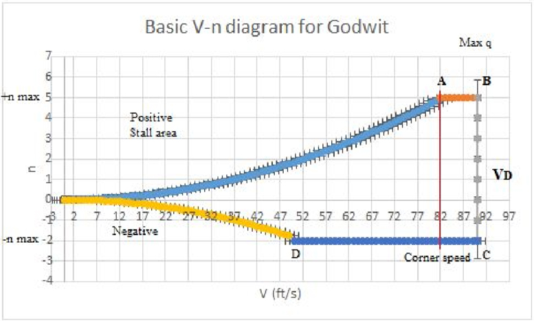
Figure 24: V-n diagram for the Godwit
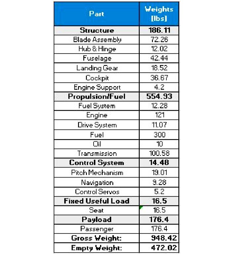
16. Weight Analysis
As can be seen in Table 9, our aircraft had a gross weight of approximately 948 lb. (430 kg) and an empty weight of 472 lb. (214 kg). This result was very close to our initial sizing approximation of 822 lb. (373 kg) gross weight.
The discrepancy corresponds to a 15.3% difference in gross weight values. The weight of all vehicles by subsystems per the SAWE RP8A Part I Group Weight Statement is shown in table 5.
Table 5: SAWE RP8A Part I Group Weight Statement for the Godwit
17.Longitudinal Center of Gravity Analysis
In the longitudinal center of gravity (CG) determination of the Godwit, we decided to locate the datum in the nose of the helicopter and measure the arm distance for every subsystem, payload, cockpit and fuel, as shown in Figure 40.
For this approximation to work, the blades were considered balanced. Through analysis, the CG of the vehicle at gross weight was found to lay 4.4 in. ahead of our rotor shaft. The CG was found to be 0.38in in front of the fuel tank center of gravity. Because of this changes in longitudinal CG during flight due to fuel being burned will not be noticeable.
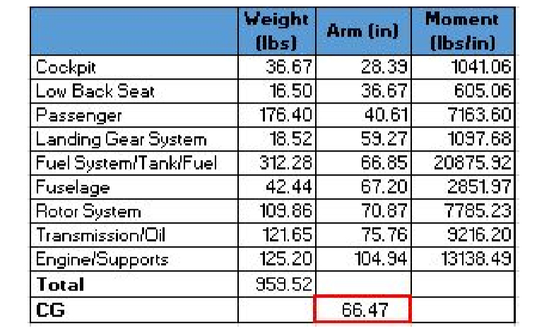
Table 6: Longitudinal Center of Gravity Calculation
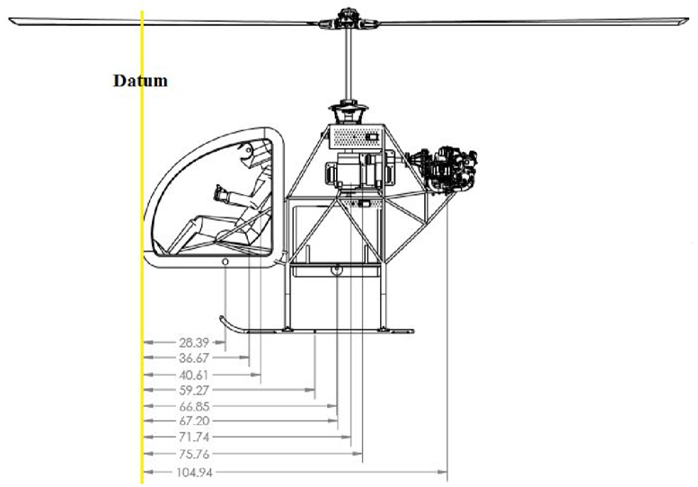
Figure 25: Moment arm for each of the considered systems
18.Lateral Center of Gravity Analysis
The lateral CG analysis was simplified because all components in the Godwit are laterally symmetric. Because of this, the lateral mass center lays in the exact center of the vehicle, as observed in Figure 41.
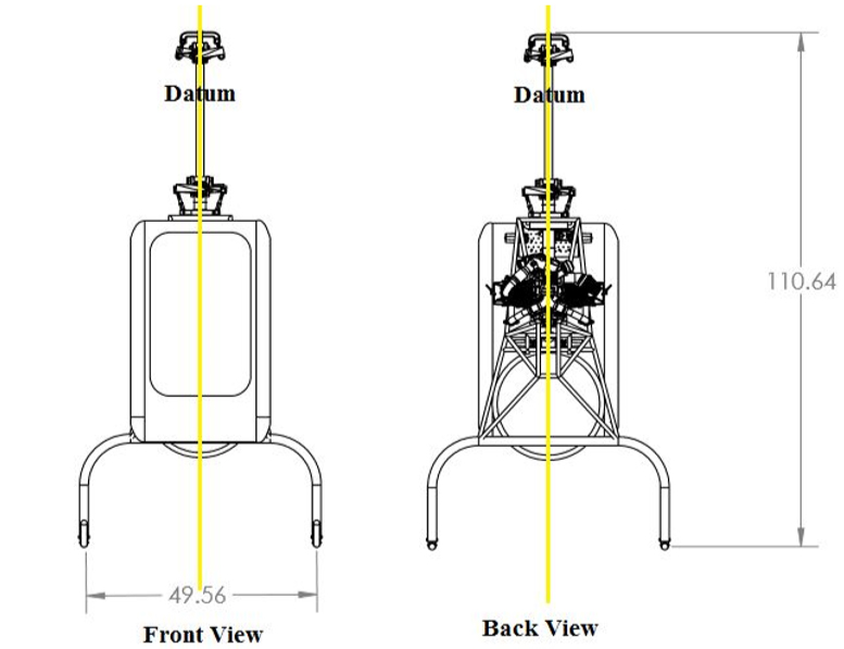
Figure 26: Lateral Center of Gravity
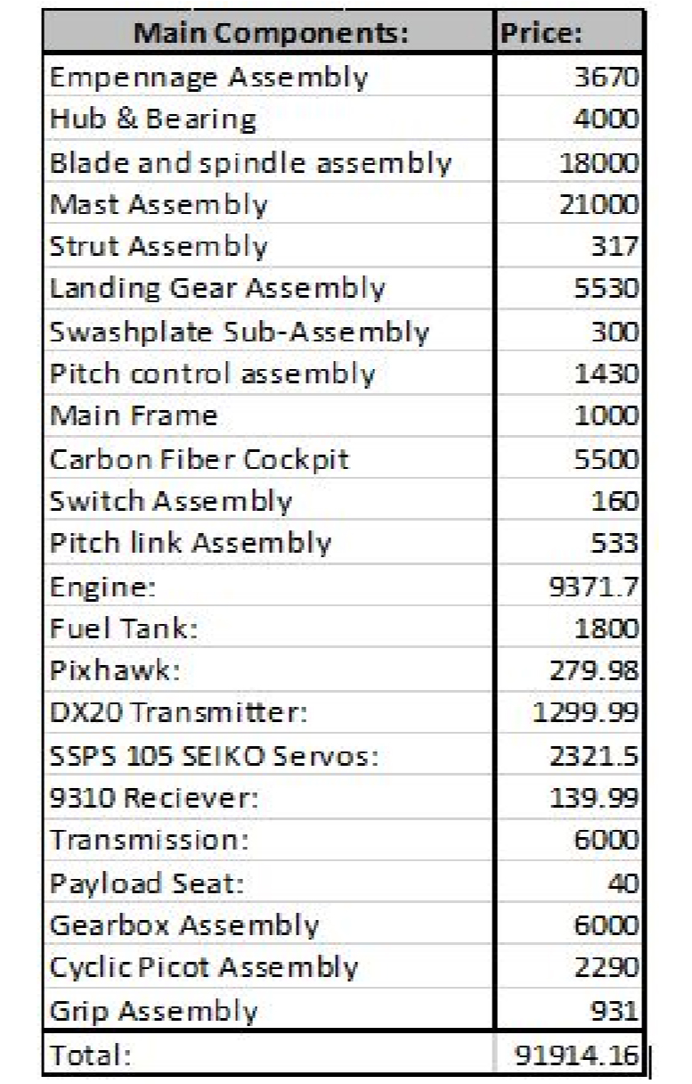
19.Unit Costs
Overview As a reference for comparison to an ultralight vehicle, the Mosquito XE has a total purchase cost of $47,500, when as per Table 7, the Godwit would cost an estimate $91,914.
The main differences are in engine cost, fuel tank assembly cost, number and length of composite blades cost, and transmission cost. Conservative values were used for composite components, since composite raw materials require no machining time even though they are highly priced.
Table 7: Cost Estimates

Be the first to comment on "Polytechnic University of Puerto Rico Godwit Helicopter"