

Safari Kit Helicopter Vibration Issues Solved
Where do you start; every helicopter has vibration. Some vibrations don’t bother you or the machine, some do and then there are just some you can’t seem to get rid of. (Editor’s note: The only “Good” vibrations occur in the Beach Boys song and a cocktail shaker. OK! there are some others too.)
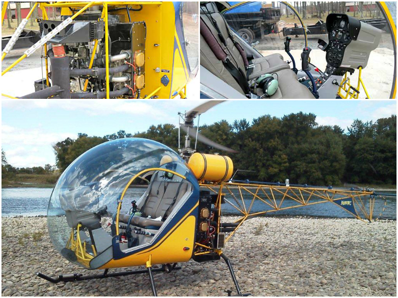
This article focuses on a trail of problems encountered with the Safari (Baby Belle) helicopter and goes through the ship, from the ground up, dealing with these issues, in hopes that those of you that apply a few of these ideas will end up with a smoother flying ship.
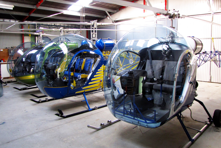
Experience with a high number of Safari Kit Helicopters, as well as other home built and commercial ships has shown that the Safari helicopter is not alone in the vibration frustration area. Here we will look at two categories of vibrations.
First, is the one-per-rev and the other, is the two-per-rev. (Editor’s note: Higher frequency vibrations can cause problems also if the cyclic stresses created, including the effects of any stress risers, exceed the “Endurance Limit”) Numerous set-ups have been tried on the Safari helicopter with notes taken before and after readings. The result is quite a list of what I think works and doesn’t work. A DSS micro balancer was used as a sensor to give accurate and consistent data.
Normally three sensors are mounted at various points over the helicopter to measure vibration and to detect any changes resulting from the various set-ups. Issues can arise where the construction of the ship, itself, has enhanced the unwanted vibration. A lot of time and effort can be spent trying to solve issues as they come up.
Some common issues, when setting up a Safari to run smooth are: Starting at the engine, check the engine for balance. Why should it be questioned, as the engine balance should be close? Well, that was an assumption made on one ship having a lot of trouble sorting out two-per-rev and a bad seat vibration.
As it turned out, the builder had assembled the starter ring gear in the wrong place (forced it over to the wrong place on the locating pin) and it was very difficult to get the engine smooth. This affected the tail rotor stabilizer, plus the shaking could be felt through the cabin.
In flight, the imbalance created a vibration through the tanks so the compass, mounted on the instrument panel, spun more like a generator. It is possible to statically balance the engine fan and clutch assembly by themselves. Experience has shown that quite often weight adjustments are needed.
The static balancing is possible by using two planer blade knives with a boss spun in the lathe to take the center pivot. However the entire assembly, engine, clutch, flywheel and fan in the operational mode needs to be checked.
Here is a process:
-
Mount an accelerometer below the starter gear, pointing towards the crankshaft.
-
Put reflector tape on one of the fan blades or clutch hub, and mount your photocell to look directly at the reflector tape.
-
Tie the blades down and run the engine up to 2750 rpm. Try to do it quickly as the plugs can get fouled easily with no load on the engine.
-
Aim for under 0.1 IPS. If you need to put weight on, use the ¼-inch holes in the starter ring gear with which to balance. (Editor’s note: Since the tail rotor drive shaft also spins at this rpm, it should be disconnected for this test to minimize the number of vibration sources)
Note: If you can do the engine balance check without the gear box installed, you have an even better option for separating just who is doing the shaking.
-
It pays to check the clutch shoes as differing weights have been found with variations as high as 20 grams and that is noticeable when the ship is running.
Now balance the tail rotor Have the helicopter running on the grass or with some soft pads under the skids at four points – rubber mats or carpets also work well.
Try to get the balance to under 0.2 (Editor’s note: There seems to be a critical speed associated in the tail boom or tail rotor drive. Balancing at 1600 engine rpm requires the correction weight to be added opposite the velocimeter, while balancing at 2700 engine rpm requires that the correction weight be added to the same side as the velocimeter. The 180-degree phase shift in the phase angle measurement indicates the existence of a critical speed somewhere between 1600 and 2700. This is probably why the balancing works much better to have the helicopter on grass or vibration absorbing pads) At this stage, you should have checked that all your controls are tight and all rod ends are without play.
If there is any looseness, some of the attempted adjustments can be masked. Go through the alignment procedure to set up your main rotor blades. Set and then lock them with two-degree negative pitch. My experience, with just pilot and low fuel, is that ½ degree negative blade pitch is not enough to set the blades for an auto rotation.
Using CHR’s (Murray Sweet’s) concept for a laser to clamp on the rotor head spindle and line each blade is a lot easier than using a string line and quicker to check for your lead lag, Thanks Murray!
Helicopter Main Rotor Blade Tracking
This can be done at any rpm above ½ to full. Use a stick, with “bearing blue” on a piece of rubber, or permanent marker rubbed onto the stick. Put the machine into a hover, or until the skids are light on the ground, and using a tracking stick or tracking lights, mark or note the closeness to one level-plane the two blade tips pass. (Editor’s Note: The use of the single color tracking stick involves bringing the “Bearing Blue” on the end of the stick up underneath the spinning blade, which will mark the higher tracking blade less than the lower tracking blade. Adjustments are made until both marks are the same.)
Note: If you want a good set of tracking lights, Kevin Lund of RotorWay, Australia has the best I have used so far. You are able to use them in the brightest of sunlight. Just make sure the batteries are up to their current voltage.
So, once the blades are tracked you can check your rotor balance. Try for below 0.2, and it is normally quite easy to achieve below 0.1. You may have chosen to add trim tabs to your blades. If not, it is possible that in forward flight the blades may go out of track. This creates a problem. Without the trim tabs, you can only compromise and end up with blades not tracking well at either hover or forward flight, but this is better than no compromise.
With trim tabs you can stick track in a hover and adjust the trim tabs for forward flight issues. (Editor’s note: While my Baby Belle blades do not have trim tabs, the ship can fly to 90mph without any increasing vertical vibration caused by tracking issues. I’m lucky. Most certified ships use trim tabs to account for slight variations in aerodynamics of the set of blades.)
So now we have tail rotor balanced, engine balanced, main rotor blades balanced and the ship tracked in hover. The last step will be to sort out forward flight vibration or two-per rev. This is the most significant since the ship flies in this mode most of the time. Any adverse effects are noticed more so in this mode. (Editor’s note: All two bladed rotors generate two-per vibrations. The best you can do is get the cabin and controls where the pilot sits not to feel it.)
By mounting the accelerometer on the Safari’s instrument panel frame work, on the co-pilots side, pointing up or down and with the photocell on the swash, as for the initial mast balance, you will be able to pick up any changes to your initial reference reading you received on your first run. (Editor’s Note: To get the balancer to read directly the amplitude of the 2/rev measurements, it is necessary to add a second reflective tape, preferably 180-degrees from the first one. Otherwise, the balancer will filter the accelerometer readings to 1/rev.)
Note: If for any reason you think you have stuffed your rotor head bearings (due to overloading or leaving the blades out of track for too long), and for a number of other reasons, you need to check them. This is most easily accomplished by disconnecting the pitch links and rolling the blades around on the grip; if they feel lumpy then you need to change them. If the blade movement does feel lumpy and it is not corrected, this will mask the tracking of the blades.
It will appear as though they are tracking correctly, as the balls ride in their detents in the damaged race, but the ship will still fly with a real bad two-per vibration. (Editor’s note: I moved my battery out from under the passenger’s seat to in front of the instrument panel similar to the Bell 47 and now have nearly zero vertical two-rev. Claude Lescure, a Safari owner in France, put a weight on a spring arm out in front of the passenger’s foot pegs and got similar results. However others have tried this with little affect.) Here are a few ideas that could assist you in getting your ship smoother.
Helicopter Fuel Tank bracing
The original factory bracing was not enough and the tanks can cave in where the brace was placed between the two tanks. To correct, take the top support across the top of the two tanks and secure through the tank clamps, then run one or two cross braces from this new brace, down to the base of the rear tank mounts. (Editor’s Note: The second brace caused my vibration to increase, so only one brace was used. Different helicopters, different results)
Helicopter Skids
On the underside of the skid sockets, where the extra tube is on the outside of the socket, you can drill and tap these to take a ¼ UNF bolt, with a locknut. Remove the skids and skid legs, which can be done one at a time; drill out and tap.
Refit skid legs and tighten the bolt up against the skid leg, finally locking the lock nut. This does help when the skid sockets wear and the skids start shaking, passing a shake through to the cabin. The rear ones don’t cause too much trouble, but I do it anyway.

A variety of bracing ideas have been tried to stop the skids shaking – going from the front of one co-pilot skid and up to the skid socket and then over to the pilot’s side. This procedure, as well as a number of other techniques, has appeared to work. However, though they’ve stopped the skids moving, the vibration or shake is simply transferred into the cabin and the DSS confirms that the two-per is the same.
Helicopter Tail Boom
Two 1¼-inches x .035 x 7-foot long, 4130 tubes were attached from the two bottom tail boom mounts back to the second station. If you are building a ship from a new kit, a tab can be welded where these tubes will mount, close to the second station or a clamp type mount can be made to retrofit onto your completed boom.
This modification eliminates most of the shake, which can occur in a quick stop or rapid descent with a quick arrest of the collective. Particularly noticeable was the shake when trying to do a quick stop at a speed of 50-knots before this modification.
Take a look at the Bell 47 and notice how straight the bottom tubes of the tail boom are compared to the Safari, which has quite a dogleg. (Editor’s Note: A closer look at the Bell 47 tail boom will show a slightly different pattern in bracing and also a change in tubing wall thickness toward the rear. Also the natural resonant frequency of the Bell’s tail boom is much lower than that of the Safari)
Helicopter Rotor Blade Differences

Not many of you will now be running the curved tip blades but some sets of these are apparently a source of two-per-rev. Reading differences of as much as one to two IPs. This was discovered after fitting a set of new square tip blades onto a ship that was having trouble when it was fitted with the curved tips. The good result was the shake reduction, the bad was a large hole in his check book for a new set of blades.
Helicopter Cabin
Make sure the floor is mounted securely and none of the body panels can move anywhere. If anything is able to move, add more rivets, even if you have to rivet the floor to the frame underneath, it will do no harm and this will stiffen the area. Rivets have been observed to have popped off the floor resulting in a cabin that you can grab hold of and push side-to-side.
Instrument Panel
Take note – this is a big deal. This is a recent discovery in solving a lot of two-per-shake, and probably the most overlooked. The greatest effect recently noticed in lowering the two-per-rev occurred after completely removing the panel and fitting a new one in place. When one builds the panel it is necessary to make sure it is not too high.
The first Bell 47 helicopters had an issue with a bad shake. A decision was made to lower the height of the panel, which solved the problem. I heard this from a very old mechanic who had worked on the very first Bell 47s we had in New Zealand.
The objective is to try to aim for 30 inches max to the top of the panel. My current panels follow the R22 helicopter idea with a seven-hole panel top, and then they are extended down for radios, other switches and gauges. The other plus is that visibility is a lot more out the front as well. Solid mount the panel face and don’t use rubber mounts or sponge rubber behind the panel. I am not a fan of the deep Safari pod.
If it’s possible make a shallower one. Once all the vibration issues are sorted out, your gauges should all be readable and the compass, if mounted on top of your dash, should not go round like a generator, all by itself. If these still show vibration you need to fix the console where it butts up against the kick panel.
Riveting angle brackets from the sides and top of the panel to the kick panel, making sure, that if necessary, this joining bracket can be riveted to the frame behind the aluminum kick sheet. Be sure that all panels are fixed top and bottom and sides. If only the sides are done, it is possible to shove the panel sideways; watching it move. If you mount the compass on top, make sure that the top of the panel is solid.
Any deflection or wobble will cause the compass to spin on its own. So, basically when you have finished, you should not be able to rock the panel in any direction. If you can, try to add some more stiffening to keep it from moving. Don’t build the console too low (below the center collective); leave yourself about 1- ½-inches as this gives a bit of rigidity to everything. Try for about four-inches wide – this part of the Safari seems to have a large affect on two-per.
Get it right and you will be on the road to smoother flying. There have been some ships with IPS as high as four and using some of these changes brought them down to less than two IPS or better. Very little skid movement, very little door frame movement (copilots side), floor not jumping up and down, gauges and compass sitting smooth while you are cruising at 70-knots, then you have achieved a relatively smooth ship and should be a happy camper.
If it is any better than that, then you have a bonus. Go out and enjoy your flying and come back with some good stories to tell. All the Safaris in New Zealand that have been built here, fly well but I will admit some have given me trying moments and I wonder if I am ever going to sort out all the issues at hand.
Footnote, In general Safaris are most of what I work on and I try to make a living by doing that, but if you have a helicopter project that is stalled and needs finishing I am available to help you get it done. The world is only a small place when you connect it with email and commercial jet airliners these days, so perhaps I will be meeting with some of you and will enjoy great helicopter smiles when your project gets smoothly off the ground.


Be the first to comment on "Taming Vibrations In The Safari Kit Helicopter"