
NOTE: This is the original assembly manual draft for the Mosquito Air kit helicopter and not a current approved and updated manual. Aviators and pilots should follow the factory recommendations and use their latest release of assembly manual. This manual was shared directly with Redback Aviation via CD from John Uptigrove (deceased) around the year 2000. For further information please contact Composite FX in the USA
INDEX
THINGS TO KNOW BEFORE YOU START
► Read each section through completely to be sure you understand what you are doing before you start the work.
► Numbers in brackets eg. (13-01) refer to part numbers. The first two digits of the part number refers to the drawing on which it is located.
► Two letter followed by a number eg. (FF-1) refer to picture numbers. Pictures are located at the back of the drawing set.
► All dimensions are in inches unless otherwise noted.
► Fully dimensioned parts in the drawings are for fabrication by the builder from the materials provided. Many of these parts are already pre-cut and pilot drilled requiring finishing by the builder. All non-dimensioned parts and sub assemblies are provided complete and are provided in the drawings to assist in identifying the parts.
► All cutting and drilling must be finished by smoothing with a deburring tool, files and/or sandpaper/Scotchbrite to ensure that there are absolutely no nicks in the material. This is especially true around rivet holes and in the crotches at the end of support angles.
► Any vice used for holding parts must be soft jawed to prevent marking the part. There must be no nicks or scratches left on the parts.
► The best and fastest way to cut aluminum is with a standard wood cutting chop saw and table saw. The saws should have carbide tipped blades with a high tooth count. Aluminum cutting blades are readily available and make the best cut.
Spray a little WD-40 on the cut line before cutting to get a smoother cut and prevent clogging the saw blade. After cutting the edges must be smoothed with a file and sandpaper until no nicks or scratches remain.
► To mark hole locations set the caliper to the distance from the center of the hole to the edge of the part. Scribe a small light line on the part at the correct distance in from each edge using the edge as a guide to form a small “X”. Punch mark the center and drill.
► All laser cut, preformed frame and controls parts have rough edges which must be filed/sanded smooth prior to final installation. Final sanding should leave no nicks in the material and should be done along the axis of the parts, not across it. Most of these parts have small pilot holes which must be drilled to size after bending when bending is required.
► Where referred to in the instructions or drawings, the left side of the helicopter is the left when sitting in the seat and facing forward.
► All bolts and nuts must have a washer underneath them unless otherwise noted. On bolts threaded into aluminum parts a lock washer must be added between the head and the plain washer unless otherwise noted.
A washer is not required under the bolt head or nut if it is fastening a spacer, the ball of a rod end or a bearing race. All bolts threaded into aluminum must have a drop of thread-locker placed on the end of the bolt before final installation.
► Where it is difficult to hold a nut in place because of a confined space such as inside the tail boom or mast, put electrical tape over the end of a box end wrench and push the nut into the box end and then use the wrench to hold the nut in place.
► To “reverse thread” nylon locknuts onto rod ends and threaded rods, first thread the locknut onto the threads the proper way about 1/2″. Remove the nut and place it in a box end wrench. Thread the nut back on with the nylon end first pushing with your thumb on the nut and holding the nut straight with the box end while turning.
► Teflon lined rod ends are often excessively tight when received. To loosen the ball find a correct size socket from a socket set such that when placed on the housing around the ball, it will just clear the ball. The socket should rest on the metal liner inside the outer housing but not be touching the ball.
Place the assembly in a soft jawed vice so that one jaw is pushing on a flat on the ball and the other is pushing on the socket. Tighten the vice, loosen and check the ball tightness. You should be able to rotate the ball with your fingers with a little effort. Redo if needed until the correct tightness is achieved.
► The bend reference line referred to in the drawings and manual is to assist in positioning the 3/8 bending mandrel. The mandrel is made in the tools section from a 3/4 x 3/4 aluminum square bar which then has one corner rounded off to a 3/8″ radius. Draw the reference line on the part. Place the mandrel on the side of the line with the “X” on the drawings.
Place the part and mandrel in a vice with the section to be curved sticking out of the vice. The reference line should be level with the top of the mandrel. Use your hands on long parts or a hammer against a block of wood on small parts to gradually bend the part. Refer to drawing 60 for a drawing of how to place the mandrel.
► Never drill holes in a part that is to be bent before bending the part. Mark and punch mark the holes, bend the part and then drill out the holes. On pre-cut parts, bend the part and then drill out the small pilot holes.
► When cutting parts out of plate that require bending, always cut the part so that the bend will be perpendicular or nearly perpendicular to the direction of the “grain” of the plate. The “grain” is the fine lines left by the mill roller on the plate.
► Dimension “X” referred to in the drawings and manual is a dimension incorporated to account for the different weight of different pilots. It is determined from the following chart:
| Weight +/- 10lbs | Dimension “X” |
|---|---|
| 120 | 20.5″ |
| 130 | 19″ |
| 150 | 16.5″ |
| 170 | 14.5″ |
| 190 | 13″ |
| 210 | 12″ |
| 230 | 11″ |
| 250 | 10″ |
► If you have any questions contact: Composite FX in the USA
I. FABRICATION
A. TOOLS
1. Required Tools
The following tools are required to assemble the Mosquito:
- Band saw with wood cutting or steel cutting blade
- Standard wood cutting chop saw with carbide tipped or special aluminum cutting blade
- Standard wood cutting table saw with carbide tipped or special aluminum cutting blade
- Drill Press
- Face or Belt Sander
- Hand Drill
- Digital Level
- Files
- Punch
- Hammer
- De-burring Tool
- 3″, 5″, 8″ clamps
- 1/4″ capacity riveter (pneumatic or bolt cutter type)
- Standard hand riveter (3/16″ capacity)
- Press
- Soldering iron
- Welder (for exhaust system)
B. LANDING GEAR
1. Rear Leg Fabrication (11-02)
-
Wear a mouth mask to prevent inhaling glass fibers. Use a band saw or chop saw to follow the lines scribed into the top and edge of the leg. Once the angles are cut the radius in the top of the leg can be filed out or cut by the band saw with the table set at the correct angle. Check the fit of the radius against the mast as you go to be sure you get a smooth fit.
-
Use a chop and band saw to cut and shape one of the aluminum rear leg inserts (11-10). Face sand or file down the sides and corners as required to fit the insert into the leg. Insert it into the leg in the position shown on the frame assembly drawing #10 Section E. The single sided tab extending off the insert should be positioned toward the top of the leg against the rear side of the leg. Use a tape measure inside the tube to ensure it is in the correct location. Place a clamp on the outside of the tube to hold the insert in place.
-
Using a drill press, drill through the small 1/8″ pilot hole into the rear leg and leg insert with a 3/16″ bit. Drill again with a 3/8″ bit completely through both sides of the tube. Smooth and de-burr the holes.
-
Loosen the clamp and remove the leg insert from the leg. De-burr the holes in the insert. Place a generous amount of silicon glue in the inside of insert on the 3/8″ holes. Place the leg pin spacer (17-02) into the insert between the 3/8″ holes. Insert the AN6-31A bolt into the insert through the spacer to hold in place while curing.
-
After the glue has cured remove the bolt from the insert and reinstall the insert into the leg. Temporarily insert the bolt to hold the insert in place if required.
-
Use a chop and/or band saw to cut the rear foot pad brackets (14-07) from a section of 1″x1″ aluminum angle provided. Use a caliper to mark the hole locations and center punch and drill. Radius the corners with a face sander and smooth and de-burr all holes and edges with a de-burring tool and file as required. Repeat for the other three brackets.
-
Clamp two of the brackets to the bottom of one of the rear legs as shown on drawing #10. The bottom of the brackets should be flush with both the bottom edge and end of the leg. Use a 3/16″ bit to drill out the rivet holes through the brackets into the leg. Use 3/16 x 1/4 grip rivets to fix the pads in place.
-
Place a mark in the center of one of the foot pads (17-03) provided one inch from the rear edge. This will be the rivet hole for the rear most rivet connecting the foot pad brackets to the foot pad. Use a protractor to draw a line toward the outside of the foot pad at 30 degrees from the outer edge. The rivet hole for the outer most rivet in the pad will be along this line.
-
Drill the hole for the rear most rivet where marked. Use a spare 10-32 cap screw and nut to attach the pad to the leg brackets. Orient the pad so that the 30 deg line runs through the center of the outermost rivet hole in the leg brackets. Clamp the pad in this position and drill out the remaining five holes into the pad.
-
Remove the pad and use a 3/8″ bit to drill a countersink into the bottom of each of the six holes in the pad. The countersink should be deep enough to allow the head of the countersunk rivets placed into it to be flush with the bottom surface of the pad. When all countersinks are at the correct depth place the leg back on the pad and rivet up through the bottom of the pad with 3/16 x1/8 grip countersunk rivets.
- Repeat the above procedure for the opposite rear leg.
2. Front Leg Fabrication (11-01)
-
Cut out the front leg following the scribed lines as with the rear legs. Remember to wear a mouth mask.
-
Cut and shape the front leg insert and foot pedal insert (11-08,11-09). Insert the front leg insert into the leg and clamp in place if required.
-
Using a drill press drill through the lower pilot hole in the side of the leg with a 3/16″ bit followed by a 3/8″ bit. Drill through the upper hole 1-1/4″ above it with a 17/64″ bit. Remove the insert and de-burr it as required. Place and retain the leg pin spacer (17-02) in the insert as done for the rear legs. Reinstall the insert into the leg and with the 3/8″ bolt in place fasten 1/4 x 1/4 grip rivets into the 17/64″ holes.
-
Insert the foot pedal insert (11-08) into the leg and slide in a couple of inches so that it is completely inside the leg. Its final location will be determined during the assembly stage.
-
Fabricate the two front foot pad brackets (14-06) from 1-1/2 x 1-1/2. Rivet the front foot pad brackets to the front leg. The bottom of the bracket should be flush with the bottom of the leg edge. The back of the brackets should coincide with the point at which the bottom surface of the leg touches the floor.
-
Place the pad on the leg such as shown in the drawings such that the front of the leg fits up against the upward curve of the pad. File the leg as required to make this a good fit. Clamp the brackets to the pad and drill out the holes for the rivets into the pad. Countersink the bottom of the pad as was done with the rear pad to prepare for riveting but do not rivet the pad to the brackets at this point.
3. Leg braces (12-05, 12-06, 12-07)
-
Use a file and sandpaper to smooth the edges and surfaces of one of the pre-cut leg braces to a clean finish.
-
Cut the reinforcement plates (12-08) from the 1/8″ sheet provided. File/face sand to the correct size. All edges should be smooth when finished. The rounded end of the reinforcement should be left square and will be finished after it has been attached to the brace and bent.
-
Clamp the finished plate to the back of the brace so that the reinforcement plate extends beyond the brace by 1/8″. Drill rivet holes but do not drill through the bolt hole yet. Install 3/16×1/4 grip rivets with the head of the rivet on the brace side of the hole.
-
Place the 3/8″ bending mandrel (60-02) in the soft jawed vice along with the reinforced end of the brace. The short end of the brace should be in the vice with the bend orientation line lined up with the top of the mandrel. The mandrel must stop short of the 1″ leg of the angle or it will interfere with the angle while being bent. (FF-1)
-
Place one hand on the reinforcement plate and another about 1 foot up the leg. Using a pre-cut angle template or protractor as a reference, bend to the angle shown in the drawing. (FF-2)
-
Use the band saw and face sander to round the end of the reinforcement to match the brace. Drill through the 1/16″ pilot leg pin hole with a 3/8″ bit and finish (de-burr and smooth). Repeat for the opposite end of the brace.
-
Repeat the above procedure for the other two leg braces.
4. Leg attachment brackets (14-01, 14-02)
-
Cut out the front leg angle bracket (14-01) from the 1/8″ plate provided as per the drawing. Mark the hole locations using a caliper set to the correct dimension as shown in the drawing. Do this prior to rounding the corners of the bracket. Scribe marks should be small enough to be drilled out when the hole is drilled. Punch mark but do not drill the holes yet. Draw a pencil line across the plate at the “bend orientation line” as shown in the drawing.
-
Place the bracket and the 3/8″ bending mandrel (60-02) in a soft jawed vice with the short end of the bracket protruding from the top of the vice.
-
Using a hammer and a wood block as a buffer, bend the bracket around the mandrel until it reaches 45 deg. Use an angle template or protractor for reference. Be sure to place the wood block near the bend point on the bracket to ensure the bend occurs around the mandrel and not further up the bracket.
-
Drill the 1/4″ holes in the bracket and finish (de-burr and smooth).
-
Repeat above for the opposite bracket keeping in mind that the bend in the second bracket will be in the opposite direction.
-
Repeat above for the four rear leg attachment brackets.
C. SUPPORTS
1. Sprocket Supports (13-01, 13-02)
-
Use a file and sandpaper to smooth the edges and surfaces of one of the precut sprocket supports to a clean, smooth finish.
-
Obtain the 2″ radius bending mandrel (60-03). Clamp the end of the support in a soft jawed vice with the mandrel so that the support is protruding out of the vice and is at right angles to the mandrel. Bend the support around the mandrel until it contacts the radius cutout. The curve should now fit the curve of the mast very closely.
-
Drill out the 1/16″ pilot holes in the web and finish.
-
Repeat the above steps for the opposite sprocket support.
2. Tail Boom Supports (12-01, 12-02)
-
Use a file and sandpaper to smooth the edges and surfaces of one of the tail boom supports to a clean, smooth finish.
-
Use the procedure followed above for the sprocket support to curve the end of tail boom support to fit the mast. Drill out the pilot holes and finish.
-
Repeat the above steps for the opposite tail boom support.
3. Support Braces (12-03, 12-04, 13-03, 13-04)
-
Smooth and finish the sprocket support braces. Drill out the pilot holes and finish.
-
Repeat for tail boom support braces.
4. Engine Supports (15-04)
-
Use a band saw with a narrow blade to cut along the scribed lines on the 2x2x1/8 square tube for the upper and lower engine supports. Check the fit of the cutout on the mast and file/sand as required to ensure a good fit.
-
Use an accurate 7/8″ hole saw in a drill press to cut a 7/8″ hole in both ends of the support using the pre-drilled 1/8” holes as guides. De-burr and smooth the holes and edges.
5. Engine Support Bracket (15-05)
-
Cut and shape the part as shown in the drawings. Mark and punch mark holes but do not drill.
-
Place the bracket in the vice with the 2″ bending mandrel. Using a block of wood as a buffer, hammer the protruding side of the angle around the mandrel. Drill out the 3/16″ holes and finish.
-
Repeat for the remaining three brackets.
6. Collective Mounts (16-11, 16-12)
-
Use a file and sandpaper to smooth the edges of the pre-cut collective mounts to a clean finish.
-
Place a mount in the vice with the 3/8″ bending mandrel on the “X” side of the bend reference line. Bend to approximately 42 degrees using an angle template. Final minor adjustments to the bend angle can be made once the mount is attached to the mast.
-
Place the mount in the vice with the 2″ bending mandrel. The entire mount should protrude out of the vice. Use a hammer and the corner of a wood block placed on the inside of the bend made above to curve the mount around the mandrel. Take care not to straighten the first bend. Drill out the 1/16″ pilot holes to 3/16″ and finish.
7. Upper Seat Supports (13-06, 13-07)
-
Cut and shape the part as shown in the drawings. Be sure the point at which the tapered portion of the top of the angle meets the web is smoothly rounded and free of nicks.
-
Mark and punch mark all holes but do not drill. Place the support in the vice with the 2″ bending mandrel and bend around the curve as shown in the drawings. Drill out all holes.
-
Repeat for the opposite support.
8. Connector Mounts (16-03 to 16-08)
-
Smooth and finish the connector mounts.
-
Drill out the pilot holes to the correct size and finish.
9. Tail Rotor Guard (16-10)
-
Smooth and finish the pre-cut part.
-
Place the 3/8″ bending mandrel at the “V” notch at the lower end of the guard and bend the 1.5″ tab to close up the 60 degree angle.
10. Fuel Tank Supports (15-06)
-
Use a band saw to cut along the marked lines for the fuel tank cutouts and drill out the pilot holes to 3/16″.
-
Smooth and finish the holes and edges
11. Other Frame Parts
-
By now you should have a good grasp of how to fabricate the basic components. Complete the remaining frame parts shown in parts list as per the drawings using techniques similar to those above.
D. CONTROL COMPONENTS
1. Foot Pedals (46-01)
-
Fabricate each of the four components of the foot pedals as shown in the drawings. Use a caliper to locate the holes and punch mark.
-
Assemble the components using small clamps ensuring that you leave a rivet hole open at each corner so that it can be drilled and riveted. Use a square in each corner to ensure the pedal is square, adjust as required. Drill and rivet one hole in each corner using 3/16 x 1/4 grip rivets. Remove the clamps and repeat with the second hole in each corner. Repeat for the second pedal.
-
Fabricate each of the pedal mounts (46-02) and control mount (46-03) for the right pedal. Attach to the pedals with 3/16 x 1/4 grip rivets as shown in the drawing.
2. Other Control Components
Complete the remaining control components shown in the parts list as per the drawings using techniques learned above.
II ASSEMBLY
A. MAIN MAST
1. Sprocket Supports
-
Observe the four lines running the length of the mast (11-07). The line running through the narrow swash plate guide slot is the rear line as this faces the rear of the helicopter. The front line runs through the larger control entry slot at the bottom of the mast. The other two are designated as quarter lines. These lines can be wiped off after assembly of the frame.
-
Using a good quality tape measure, mark a light line 1-3/16″ down from the top of the main mast on the quarter line on both sides. Mark a second set of lines 15-1/16″ down on both quarter lines with a fine felt pen. This is the tail boom support location. Mark a third and fourth set of lines 12-9/16″ and 20-1/2″ up from the bottom of the mast midway between the quarter and rear lines on both sides. These are the engine support locations.
-
Use AN4-10A bolts with thicker AN960-416 washers under the heads, bolt the lower bearing housing (25-02) to the slots in the rear end of both sprocket supports (13-01, 13-02). The sprocket mount should be slid to the front of the slots on both supports.
-
Slide the sprocket support assembly over the top of the mast and down so that the top of the supports lines up with the top set of marks. The supports should now be protruding at approx. 90 deg straight out from the mast with the rear line centered approximately between them. Clamp the supports to the mast. Place small clamps on the mast up against the top of each support to provide a positive location for future moves of the supports. (MA-1)
-
Clamp one of the support braces (13-03 or 13-04) to the side of the support and to the side of the mast. The top of the brace should be flush with the rear end of the support and up under the flange of the “T”. The holes in the bottom of the brace should be centered on the quarter line of the mast. (MA-2)
-
Cut two 6″ sections of left over 1x1x1/8″ angle. Clamp one section to the underside of the supports directly next to the mast. Clamp the second section under the support about 8″ away from the mast so it will not interfere with the support brace.
-
Place an accurate 18″ square under the supports so that one leg is resting along the mast and the other is up against the sections cut above. Loosen the mast clamp on the support brace and slide the brace up or down the mast as required to make the sprocket mount perfectly perpendicular to the mast. Check to see that the supports are still positioned properly on the mast. Tighten the support brace clamp. (MA-3)
-
Center the support brace plate (13-05) on top of the supports as accurately as possible. The plate should butt up to the mast. Clamp in place. Drill the six 1/4″ holes through the supports and install four 1/4″ temporary bolts in the corners.
-
Set the caliper to 3.094″ and, measuring in from the edge of the support, place a small mark on the support brace plate right next to the mast. Measure in from the edge of the opposite support and place another mark. This should coincide exactly with the previous mark. If it doesn’t then the center is the point midway between the two marks. This point should be directly next to and exactly on the center of the rear line on the mast. If it is not, you will need to slightly loosen the support clamps on the mast and rotate the supports until it is. After making the move the supports will have to be rechecked for square and positioning.
-
Once the supports are correctly positioned and square, drill a 1/4″ hole through one of the open holes of the support and through the mast. Install a temporary bolt. Repeat for the opposite support. While continuously checking for proper positioning and square of the components, drill through the holes in the support brace into the support and into the mast with a 17/64″ drill bit and install 1/4 x 1/4 grip rivets. Install the second brace on the opposite side and clamp into the correct position. Drill out the holes with a 17/64″ bit and install 1/4 x 1/4 grip rivets.
-
Remove the bolts in the sprocket support brace plate, drill out to 17/64″ and replace with 1/4 x 1/4 grip rivets one at a time. Install rivets in the two center holes in the plate. Remove the 4-3/8″ angle sections.
2. Tail Boom Supports and Braces (12-01, 12-02, 12-03, 12-04)
-
Lay the supports (12-01, 12-02) on a flat surface with the tops facing down. Place the assembly spacer (60-01) provided between the third holes in from the rear of the supports and fasten in place with the 1/4 x 5″ bolt provided.
-
Slide the supports onto the bottom of the mast and up to the support mark made on the mast quarter line. Clamp one of the 6″ angle sections used in the sprocket support assembly across the top of the supports next to the mast and another approximately 8″ back toward the rear of the supports.
-
Place the bottom of the mast in a vice so that it is standing up vertically. Check your digital level to be sure it is calibrated correctly and use it to check the plumb of the mast. The mast should be plumb within 0.1 degree in both directions. Secure it in this position so that it will not move while it is being worked on.
-
Clamp the supports so that the top of the supports are on the marks on the quarter line. Clamp one of the support braces in the correct position below the support to help hold the support perpendicular to the mast. The quarter line should run through the center of the lower holes in the brace.
-
Set the caliper to 2.00″ and using the inside of the left sprocket support (13-01) as a guide, scribe a small, light line on the rear edge of the lower bearing housing (25-02). Repeat from the right support (13-02) to find the center of the housing.
-
With the caliper still set at 2.00″ use the same method outlined above to place a centering mark on the mast side of the assembly spacer (60-01).
-
Create a plumb bob by attaching a heavy nut or some other weight to the end of a piece of fine string such as fishing line. Clamp the string to the top of the lower bearing housing so that string hangs over the housing and is resting over the center-line mark you just scribed. The weight should hang near the bottom of the mast.
-
Check the following alignments of the tail boom supports.
-
The second hole in from the front of the supports should be centered on the quarter line of the mast on both supports
-
The supports should be perpendicular to the mast. Use a square resting along the mast and up under the angle sections clamped across the supports to check this alignment
-
The center line on the assembly spacer should line up precisely with the plumb bob string. Use the digital level to check that the mast is still vertical.
-
-
Once all these alignments are determined to be correct drill out the tail boom support holes into the mast to 17/64″ and install 1/4 x 1/4 grip rivets into the holes.
-
Ensure the support brace is still correctly positioned with the hole at the lower end placed directly over the quarter line of the mast and the upper end up against the bottom of the flange of the tail boom support. Drill out holes and rivet. Repeat for the opposite brace. Remove the assembly spacer and angle sections.
3. Engine mounts (15-04)
-
Place one of the engine supports on the mast with the top of the support on the mark made earlier for the upper engine support. Clamp in place leaving some room on the rear face of the support to place a square.
-
Using the dimple mark placed on the rear face of the support, place the square on the rear face of the support with the corner of the square lined up with the center of the dimple. The protruding leg of the square should now just touch the plumb bob string. Loosen the clamp and rotate the support on the mast until the square just touches the string and re tighten.
-
Clamp one of the engine support brackets (15-05) on the front of the engine support with the curved portion resting on the mast and clamp in place. Make a final alignment check and drill out the holes into the support and the mast and rivet with 3/16 x 1/4 grip rivets. Repeat for the second support bracket.
-
Repeat for the lower engine support.
4. Collective Lever Supports (16-11, 16-12)
-
Place a mark 1.188 (1-3/16″) in from the squared end of the collective torque tube (48-01) using the caliper. Position the right slave lever on the torque tube so that the outside edge of the lever lines up with the mark as shown in drawing 42. Check for squareness between the tube and lever and clamp in place. Drill out the holes and rivet with 5/32 x 1/4 grip rivets. (CL-1) *Note that picture has old style lever with two attachment brackets. New style lever and upper bracket are one piece.
-
Place the left slave lever in position next to the right and clamp. Check the distance between the levers along their full length. It should measure 1.75″ +/- .015″. Adjust as required, drill and rivet in place with 5/32 x 1/4 grip rivets.
-
Place the right slave lever bracket (48-07) inside the right slave lever and clamp to the bottom of the torque tube. Drill through the slave lever into the bracket and rivet with 5/32 x 1/4 grip rivets. Drill through the bracket into the bottom of the torque tube and rivet. Repeat for the left slave lever bracket.
-
Clamp the throttle advance lever (48-09) in place on the torque tube as shown on the drawing. Drill out the holes and rivet in place with 5/32 x 1/4 grip rivets.
-
Reverse thread two nuts onto two male 1/4″ rod ends so that .625″ of threads are protruding. Bolt the collective lever mounts (48-10) to the rod ends in their correct locations and orientation as shown in the drawings. Install the rod ends in the holes in the torque tube. (CL-2)
-
Using the caliper place two small marks 4.125″ up from the bottom of the mast half way between the quarter and rear lines on both sides.
-
Mount the collective lever assembly in place by sliding the slave levers in through the slots in the mast and positioning the top of the supports on the lines on the mast. Loosely clamp in place. Adjust the positioning of the assembly so that the slave levers stay in the center of the slots while rotating the torque tube and moving them from top to bottom. (CL-3)
-
Once positioned correctly drill through the holes in the supports into the mast and install 3/16 x 1/4 grip rivets. Unbolt the torque tube from the rods ends.
B. LANDING GEAR
-
Lay the three legs (11-01, 11-02, 11-03) and leg braces (12-05, 12-06, 12-07) on the floor in their respective positions. (LG-1) (*note: ignore attachment on front leg in picture will be added later) Use AN6-31A bolts to bolt the braces to the legs. Tighten the bolts moderately so that the legs can still be rotated but will stay in position when left alone. Lift the three legs at the center so that they form a pyramid shape. (LG-2) (*note: picture is of wheeled prototype assembly)
-
Measure up from the bottom of the mast 2-1/16″ and place a mark about 1/2″ to one side of the front line. Place a small clamp through the controls cutout such that clamp pad is above this line with the edge of the pad on the line.
-
Slide the mast between the three legs and let the clamp placed in the above section rest on the top of the front leg. The front line on the mast should be in the center of the front leg. Push the other two legs down to meet the mast. The mast should be able to stand here on its own. (LG-3)
-
Clamp the appropriate leg brackets (14-01, 14-02) on either side of each leg. The short side of the brackets should be up against the mast with the long side vertically centered on the leg. The clamp should be underneath the leg with the clamp pads on the lower holes of the brackets so that the upper hole can be accessed for drilling and riveting.
-
Slide each leg up or down until the underside of the center of each leg is at the same level as the bottom of the mast. Clamp a bracket on one side of each leg to the mast and leg. (LG-4)
-
Place adjustable straps from the top of the mast to the bottom of each of the legs. Tighten enough to maintain their position without affecting the clamps holding the leg brackets. Place the front pad under the front leg in its approximate final position.
-
With the frame in its final assembly location, place an approx. 6″ square mark on the floor around each pad. Move the frame to one side and place a small (approx. 6″x6″) section of 1/2″ plywood board on each of the marks. Use a straight edge and the digital level to check the level between each of the plywood boards. Shim under the board as required until the boards are level to 0.0 degrees with respect to each other.
-
Move the frame back on to the boards placed above. Use the digital level to check the plumb of the mast. Adjust each of the straps as required until it is plumb to within 0.1 degrees. Be sure the legs and leg brackets are still in their correct position.
-
Place a 4 foot or longer straight edge along the top of one of the sprocket supports (13-01 or 13-02). The edge of the straight edge should be against the mast and flush with the inside of the web of the support at the back (ie. parallel to the support) and positioned so that its far end is hanging out over the front leg.
-
Tie the plumb bob to the straight edge at the end overhanging the front leg so that it hangs down directly from the inside edge (or mast side) of the straight edge. The weight should hang near the floor. The string should hang 1″ from the edge of the front leg. Loosen the clamps holding the mast to the legs and rotate the mast as required to achieve this alignment. (LG-5)
-
Recheck the location of the legs, leg brackets and the plumb of the mast. Once all alignments are correct, drill out the rivet holes in the leg brackets into the legs and mast with a 17/64″ bit and place 1/4 x 1/4 grip rivets in each of the holes.
-
Use a tape measure to place a mark directly beneath the tail boom support at 1-3/32″ across from the rear line on the mast. Place a second mark at the same distance away from the rear line and 1-1/2″ below the first.
-
Place a connector mount (16-06) on the mast with the edge of the mount on the marks just made and with the top of the mount 1/8″ below the bottom of the tail boom support. The bolt hole should be on the lower side of the mount. Clamp in place, drill out the holes and rivet with 3/16 x 1/4 grip rivets.
-
Place a small amount of gap filler on a connector (17-06) and slide into place in the end of the main mast support tube. Drill four 3/16″ holes around the circumference as shown in the drawings and install 3/16 x 1/4 grip rivets.
-
Bolt the connector and tube assembly to the upper connector mount on the mast using an AN4-10A bolt. Bolt a second connector to a connector mount (16-03) and after placing gap filler on the connector, slide the connector into the lower end of the mast support strut.
-
Rotate the lower connector assembly in the strut until the mount hole in the connector mount is closest to the mast and lays along the top of the rear leg as shown in the drawings. Clamp in place. Recheck the mast to be sure it is still vertical and then drill out the holes in the connector mount into the leg and install 3/16 x 3/8 grip rivets. (LG-6)
-
Drill through the holes in the support strut into the connector and install 3/16 x 1/4 grip rivets.
-
Repeat the above for the opposite support strut.
C. TAIL BOOM
1. Drive Shaft
-
Place gap filler on a tail rotor drive shaft plug (24-05) and install into one end of the tail rotor drive shaft (24-04) until the plug is flush with the end of the shaft.
-
Place gap filler inside the non-keyed end of one of the drive couplings (24-08) and slide it onto the end of the shaft in which you just installed the plug. Be sure it has fully bottomed on the end of the shaft. Use a drill press to drill through the coupling hole straight into the center of the shaft about half way through it. Turn the shaft over and drill though the opposite side until the holes meet and continue out the other side. Place two washers under the head and gap filler on the shank of an AN3-15A bolt and install into the hole with a single washer under the nut. (TB-1)
-
Press a tail rotor drive shaft steady bearing (B-02) into its bearing housing (24-09) and secure with three 6-32 x 3/4 socket head cap screws. Press a tail rotor shaft bearing mount (24-03) into the bearing. Place the steady bearing O-rings (V-25) onto the housings. Repeat for the other two steady bearing assemblies.
-
Place pencil marks at 27″, 54-1/2″, and 82-1/2″ from the end of the coupling along the drive shaft. Slide a bearing assembly onto the shaft with the rivet hole end of the bearing mount first. Place the edge of the mount on the line closest to the coupling.
-
The mount should be snug on the shaft. If it can wiggle cut a small 1.5 x 5″ inch section of .001″ shim stock (V-08) provided and wrap around the shaft in a slight helix next to the line and try to slide the mount over it by rotating it as it moves forward. If it can still wiggle cut a longer section of shim stock. If it can’t go over the shim cut a smaller piece and try again until you achieve a snug fit.
-
With the edge of the mount on the line, drill through the holes in the mount with a 5/32″ drill and rivet with 5/32″x 1/8 grip rivet. Repeat for the remaining two housings, each on its respective line.
-
Repeat steps (a) and (b) for the coupling at the opposite end of the shaft (TB-2).
-
Obtain a section of rag that is large enough to fill up the end of the tail boom when wrapped into a ball. Use a 10′ tube or bar to push the rag the full distance through the tail boom to be sure it is clean. Saturate the rag with motor oil and repeat to lubricate the inside of the boom. Repeat this two more times.
-
Place the drive shaft into the tail boom up to the first o-ring. Continue pushing the shaft into the boom while working the o-ring into the tube by pushing on it around its circumference with a flat tool such as a putty knife as required until it slides into the boom. Repeat for the second and third bearings.
-
Slide the shaft assembly until the first bearing is at the far end of the boom to push out any excess oil. Clean up any excess oil pushed through the boom. Slide the assembly back into the boom until it is centered with the end of the couplings 1-9/16″ in from each end of the boom.
2. Tail Boom Mount
-
Use an AN3-3A bolt to fasten the tail boom spacers (17-04) to the tail boom. Place a washer and threadlocker on the bolt and place it into the 3/16″ hole at the front of the boom from the inside out. Thread it into the threaded hole in the spacer so that the spacer holes line up with the holes in the boom. Repeat for the opposite spacer.
-
Place a support behind the helicopter on which the tail boom can rest while it is being installed. Lift the tail boom into place and install AN4-10A bolts through the second hole from the rear in the tail boom support on through the second hole from the rear in the tail boom on each side. The bolts should be installed from the inside of the boom out with the nut on the outside.
-
Using the digital level, check to see that the mast is still vertical. Check the level of the boom and shim the support up or down until it is at 90 degrees to the mast. (TB-3)
-
Clamp a straight edge in the same position as used to align the mast with the front leg, except with the straight edge extending out over the tail boom with the plumb bob hanging beside the tail boom. The string should hang straight down from the inside edge of the straight edge. Move the tail boom horizontally until the edge of the boom is 7/16″ from the string. (TB-4)
-
Mount the connector mount for the tail boom supports (16-07A,B) in place on the rear legs as shown in the drawings. Drill one of the holes closest to the bottom of the leg first without pushing too hard as the drill bit drills through the aluminum insert inside the leg so as not to bend it. After drilling the first holes mount the connector in place with a 3/16 x 3/8 rivet. Drill out the remaining holes and rivet in place. The bend in the tang should point toward the outside of the helicopter.
-
Place some gap filler onto a connector (17-06) and slide it into one end of each tail boom support strut (11-06). Drill 3/16″ holes through the holes in tube into the connector. Install 3/16 x 1/4 grip rivets.
-
Bolt the struts in place onto the connectors on the back of the rear legs using AN4-10A bolts. Loosely bolt a connector to each tail boom connector mount (16-04A,B). Place gap filler on the connectors and slide each assembly into the top of the struts.
-
Lift both of the support struts into place so that the connector mounts lie along the bottom of the tail boom with the intersection of the mounts at the bottom centerline of the boom. If the connectors do not lie flat and parallel on the tail boom it may be necessary to bend the tang of the connector slightly until it will lie flat.
-
Recheck all alignments and clamp the connector mounts in place. Drill out holes and rivet with 3/16 x 1/4 grip rivets. Use caution while drilling. Do not let the drill bit push through the hole and strike the drive shaft inside.
-
Drill out as many holes in the top of the support struts as possible and install 3/16 x 1/4 grip rivets. Unbolt the top of the support struts and drill and rivet the remaining holes. Rebolt the support struts in place.
-
Install an AN4-10A in the rearmost holes of the support and tail boom from the inside of the tail boom out (ie. with the head of the bolt inside the tube). This may require a set of needlenose pliers or vice grip. It will be necessary to flex the drive shaft to the side slightly while installing the bolt in the hole.
-
Place a mark on top of and 7-1/2″ back from the back end of the tail boom. Place the control cable bracket (16-02) at the mark on top of the boom as shown in the drawings and clamp in place. Drill out the holes and rivet with 3/16 x 1/4 grip rivets taking care not to strike the drive tube inside.
-
Place a mark on the bottom and 5” back from the back end of the tail boom. Place the tail rotor guard connector mount (16-08) at the mark on the bottom of the boom as shown in the drawings and clamp. Drill out the holes and rivet with 3/16 x 1/4 grip rivets. Clean out any shavings left in the tail boom.
3. Fuel Tanks (V-46)
-
Use a hack saw to cut the threaded drain off the bottom of the tank as close to the tank as possible. Drill out the hole to ½ “. File the cut area and debur the hole until smooth.
-
Drill a second ½ ” hole at the bottom of the tank between the weld and the bevel on the end cap of the tank. Drill a third ½ ” hole in the same location except on the top of the tank. De-burr and smooth the hole edges. Shake the tank and use compressed air to remove all the filings from the tank.
-
Spread silicon glue on the outside of a rubber fuel tank bushing (V-40) and install in the first hole drilled in the drain fitting. Spread a small amount of silicon on the nipple of the fuel valve (V-42) being careful not to get any on the filter and push into the rubber bushing until it is fully seated.
-
Repeat the procedure above to place elbows (V-41) into the second and third holes drilled above. Cut a section of fuel line (V-43) and connect these two elbows (V-45). Fasten a fuel line hose clamp (V-15) on each tubing connection.
-
Repeat the procedure for the second tank but only drill one hole and install the fuel valve. The elbows for the fuel level gauge are not required.
-
Clamp the front fuel tank support (15-06) onto the tail boom support with the vertical flange next to but not touching the mast as shown in the drawings. The holes in the tank support should be over the center of the tail boom support flanges. Drill through the holes into the tail boom supports and install AN3-5A bolts.
-
Install the second support 4″ behind the first with the vertical flange toward the rear.
-
Place a T-bolt (V-47) into a tank strap (15-03) and fold the end over the bolt. Drill through the holes and install 5/32 X 1/16 grip rivets. Repeat for the other three straps. Install the straps onto the end of the tank supports with the strap underneath the support using AN3-4A bolts.
-
Slit one side of the ½ ” rubber hose (V-48) supplied down its length being careful not to cut into the opposite side. Cut into 6″ lengths and place over the curved portion of the tank support for the tank to sit on.
-
Place the tanks onto the supports with the fill connection of the tank centered between the supports and with the fuel valve elbows pointed inward. Cut four 12″ x 7/8″ strips of reinforced rubber (V-03) to place under the tank straps. Position the strips under the tanks straps and run the straps over the tanks. Place the T-bolt into the holes in the supports. Add a washer and nut and tighten until the straps are snug.
D. ROTOR SHAFT
-
Slide one of the rotorshaft end plugs (50-05) over the push tube (50-01) with the larger diameter of the plug toward the “Y” end of the push tube. The push rod holes in the plug must be oriented at 90 deg from the slot in the push tube. The fit should be a smooth slide fit with no slack between the plug and tube. If the plug fits too tight you will need to file each side of the plug hole evenly until the fit is correct.
-
Insert the tube into the rotor shaft assembly (A-03). Place the lower plug over the push tube at the bottom of the shaft in the same orientation as the upper plug. Repeat the filing procedure to get the right fit if required.
-
Insert the smaller diameter section of both plugs into the ends of the rotor shaft. Rotate the tube and plugs until the slot in the tube aligns with the hole in the pivot block at the top. Look through the rotor pin hole and rotate the tube as required to ensure the tube will not interfere with rotor pin.
-
Pull the push tube out of the lower end plug and drill through the four holes in the end of the rotor shaft into the plug using a 1/8″ bit taking care not to move the plug and not to damage the threads in the holes. Using the threadlocker, install 1/2″ long 6-40 socket head cap screws into the shaft and plug.
-
Slide the push tube back through the lower hole to ensure the upper plug is still oriented correctly. Slide the tube back out of the upper end plug and repeat the procedure on the upper plug using 3/8″ long 6-40 screws.
-
Recheck the fit of the push tube. It should slide smoothly through the plugs but should have no slack. File the plugs slightly if required to achieve this fit.
-
With the push tube in place, place the rotor pin (25-05) in the teeter block. Press the pin through the block, rotor shaft and push tube. (RS-1)
-
Bolt a modified 1/4″ female rod end (B-17B) to the rod end mount (49-07) using a 1/4 x 2 bolt with threadlocker on the threads and shank and a lock washer and plain washer under the head. The flats of the rod end should fit down into the slot in the mount.
-
Place a restraint liner (49-06) onto a flex restraint (49-08) so that the bottom and edges of restraint are flush with the restraint liner as shown in the drawings.
-
Drill through the restraint into the liner with a 5/32 bit. Counter sink the hole in the liner with a 1/4 bit as shown in the drawings. Attach the liner to the restraint with two 1/2″ long 6-40 flat head screws placed in the countersunk liner. The head of the screw should be flush with the liner. Repeat for the second restraint and liner.
-
Bolt the two restraint assemblies and rod end mount to the bottom of the push rod using AN3-15A bolts as shown in the drawings.
-
Reverse thread a locknut on the longer threaded end of each of the 1/4″ push rods (49-02) until there is 7/8″ of threads protruding below the nut. Place a spacer (47-15) on the rod and install 1/4″ modified rod ends (B-17B) on each rod. Tighten the rod ends up to each spacer.
-
Slide the push rods into the slots in the plug at the bottom of the rotor shaft up through the top of the shaft. Reverse thread nuts at the top of the rods until 9/16″ of threads protrude above each nut. Install a 1/4″ rod end (B-17A) on each rod down to the nut but do tighten.
-
Before continuing with the rotor shaft the swash plate must be assembled. Press bearing B-18 into the swash plate (49-04). Press the second bearing in place behind the first. Press the swivel (49-09) into the bearings in the swash plate taking care to properly support the bearing races and not damage the tangs on the swivel.
-
Bolt four 8-32×3/4 cap screws and two 10-32×3/4 cap screws in place in the bottom of the swash plate and swivel respectively using threadlocker and plain and lock washers on each.
-
Place a spacer (47-12) on an AN4-24A bolt with no washer. Slide the bolt into one of the rod ends on the end of one of the push rods at the bottom of the shaft assembly. Place a second spacer (47-12) on the bolt on the other side of the rod end. Set the swivel in place as shown in the drawings and push the bolt through one side of the swivel. Use needle nose pliers to insert the next spacer and push the bolt through the spacer and push tube rod end. Continue this process until the bolt is through the opposite rod end. Add a final spacer and tighten the nut in place with no washer.
-
Press a B-19 bearing into each of the butterfly levers (50-04). Put the levers together with the bearings contacting each other. Place a spacer (47-16) on each side of the lever bearings and slide into place in the Y portion of the push tube and over the rod ends as shown in the drawings. Slide an AN4-20A bolt through the push tube and bearings but do not thread on a nut.
-
Place an AN4-11A bolt through the bottom of the butterfly lever (50-04) and through each of the upper rod ends as shown in the drawings. If the bolt will not slide through both rod ends remove the butterfly lever and turn one of the rod ends on or off the rod as required until the holes line up. (RS-2)
-
At the same time check to see that the swash plate and butterfly lever are parallel. Check this by placing the swash plate perpendicular to the push tube and checking if the butterfly lever is also perpendicular. This can be done visually or using a square.
-
If the holes line up but the swash plate and lever are not parallel, back off one rod end 1/2 turn and the other on 1/2 turn until they are parallel. When the alignment is correct insert the bolts and tighten with all metal lock nuts. Fasten a nut on the butterfly lever pivot bolt.
-
Check to see that the movement of the assembly is smooth and not too tight. If it is too tight the assembly may not be correctly aligned or the rod ends themselves may be too tight. Loosen the bolts and retighten and check again. If it is still tight turn one of the rod ends on or off.
-
Remove the bolts holding the sprocket supports to the mast. Insert the rotor shaft assembly into the mast until the top of the bearing housing is flush with the top of the mast. Check the clearance between the bottom of the large sprocket and the top of the sprocket support brace. This should be no less than 1/16″. Place a clamp across the sprocket supports at the mast to hold both the supports and the rotor shaft assembly in place. Be sure the holes in the support and the mast line up exactly and that the clamp is not blocking any of the holes.
-
With a 1/4″ bit, drill through each of the holes in the sprocket support into the bearing housing taking car not to strike the rotor shaft inside the housing. Drill an additional hole on the rear line of the mast 1.5″ below the support brace.
-
Remove the clamp and the rotor shaft assembly. Drill out each of the holes in the housing to 25/64″. Counter bore each hole with a 1/2″ drill bit down 1/16″ so that the flange on the nutsert (V-28) will be flush with or below the housing surface.
-
Shake any free shavings out of the inside of the housing out through the holes. Insert the nutserts and using the nutsert tool (V-29) tighten to 15 ft-lbs. Make sure the nutsert tool presses against the nutsert and not the housing while installing. It may be necessary to bevel the outer edge of the nose of the nutsert tool down to ensure this is the case.
-
After installing all nine nutserts thread a 1/4-28 tap through each to reduce the torque required when installing the bolts. Check to see that the nutserts do not protrude above the surface of the housing. If they do use a file to make them flush.
E. MAIN ROTOR CONTROL
1. Main Mast Assembly
-
Slide a 5/16″ control tube end (47-11) into the end of one of the control tubes (50-02) until the ends are flush. Drill through the holes in the tube into the tube end and place three 5/32 x 1/8 rivets around the circumference of tube at 1/4″ axial spacings as shown on the drawings. Press firmly on the rivetter while setting the rivet to be sure the head sets up against the tube. Repeat at the other end with a 1/4″ tube end (47-10). Repeat this procedure for the other two control tubes.
-
Reverse thread a 5/16″ nut on the 5/16″ control rod (49-01) with 3/4″ of rod protruding. Reverse thread a 1/4″ nut on the opposite end of the push rod with 5/8″ of thread protruding. Thread a modified rod end (B-17B) onto the top of the control rod up to the nut. Thread the push rod into the control tube up to the nut and tighten the nut.
-
Reverse thread a 1/4″ nut on the threaded rod (49-03) with 3/4″ of thread protruding. Repeat for the opposite end of the rod with 5/8″ of thread protruding. Thread the 3/4″ end into the control tube up to the nut and tighten. Thread a rod end (B-17A) on the 5/8″ end up to the nut. Check to see that the rod ends at each end of the control tube are at right angles to each other and tighten.
-
Check the overall length of assembly from the top of one rod end to the other. This distance should be 40-7/8″ to within 1/32″. Modify as required. Repeat the procedure for a second control tube. (MC-1, MC-2)
-
The procedure for the third tube is the same except that 1/8″ should be filed or ground off the end of the threaded rod (49-03) so that it is 2-7/8″ long. The overall length of the completely assembled third tube should be 1/8″ shorter or 40-3/4″.
-
Grind a 1/4 x 2 bolt to 1.720 (1-21/32) long and bevel and clean the threads. Slide the sleeve (49-05) onto the bolt followed by a spacer (47-12). Slide the bolt into the top rod end of the shorter control tube assembly and thread into the rear of the swash plate. Use modified cap screws (50-06) to bolt the other two longer control tube assemblies into the sides of the swash plate on either side of the shorter tube. (MC-3, MC-4)
-
Press bearing B-19 into the tube side of the roll lever (48-02). Place an AN960-416 washer (1/16″ thick) in the small space between the bearings and proceed to push a second B-19 bearing into the bearing cavity on the opposite side. Use a screwdriver or other pointed device to line up the washers with the bearing bores.
-
Place a 1/4″ spacer (47-15) onto a male 1/4″ rod end (B-16) and insert the rod end into the bearings. Place a small amount of thread locker onto the end of the threads and tighten an all metal locknut on the rod end. The rod end should rotate easily in the bearings.
-
Reverse thread two 1/4″ nuts onto two male rod ends (B-16) with 5/8″ of thread protruding. Insert an AN4-17A bolt into one rod end. Place one of the pitch levers (49-10) onto the bolt as shown in the drawings followed by a washer. Slide the bolt through the roll lever rod end just installed above, a second washer, the second pitch lever and the second rod end as shown in assembly drawing A-3. Line the two pitch levers up and lightly tighten a nut on the bolt.
-
Insert a female 1/4″ rod end (B-17A) with washers on either side between the top holes of the pitch levers. Place an AN4-10A bolt through the lever hole and rod end and tighten a nut on the bolt.
-
Reverse thread two 3/16″ nuts onto two 3/16″ male rod ends (B-14) with 5/8″ of thread protruding. Install the rod ends into the rod end mount plate (48-03) as shown in the assembly drawing. Install the plate onto the two 1/4″ rod ends connected to the roll lever. Tighten on nuts and ensure all rod ends are parallel so that there is no rubbing on the levers.
-
Place the rear, shorter control tube rod end with washers on either side between the lower holes on the pitch lever and bolt in place with an AN4-10A bolt. Now tighten the AN4-17A bolt installed above attaching the pitch lever to the roll lever rod ends.
-
Place a modified cap screw (50-07) through the lower left control tube rod end. Slide a spacer (47-12) over the screw and insert into the left side of the roll lever. Place a washer and tighten an all metal locknut 1/4-28M onto the screw. Repeat for the right control tube. (MC-5, MC-6)
-
Check the rotor shaft and control assembly by placing it on its side with a support under the lower end of the control tubes so that they are parallel to the floor. The roll control tubes should be resting on the block with the pitch tube above them. (MC-7, MC-8)
-
Position the roll lever (48-02) so that it is in “neutral” position ie perpendicular to the control tubes. Now rotate the front of the lever down approx. 16 degrees which will be its final angle when installed with the torque tube running down the front leg at 16 degrees. Position the pitch lever (49-10) so that the lower section is perpendicular to the control tubes ie. the bottom of the lever is vertical.
-
With the lower controls in the “neutral” position outlined above check the swash plate. It should be in the neutral position (parallel with the drive sprocket) as well. If it is not turn the upper control tube rod ends up or down as required to bring them into alignment.
-
Check the play in the control tubes. They should be free to rotate on their axis to the full extent permitted by the rod end at one end ie. rotation should not be limited in one direction by the rod end at one end and in the other direction by the rod end at the other thereby limiting the overall rotational freedom of the tube. This is very important.
-
Finally, check again that the butterfly lever (50-04) is in the neutral position when the lower controls and swash plate are in the neutral position. Once the controls are properly aligned as outlined above and all nuts are tightened, remove the upper control tube cap screws in the swash plate one at a time, place a drop of threadlocker on the end threads while still in the rod ends and reinstall. Remove the bolt and spacer from the pitch control tube (rearmost tube) and set aside for later.
-
Cut three 6″ lengths of foam tubing wrap (V-11). Place them on the control tubes so that approx. 4″ is on the tube and 2″ is on the rod. Use a tie wrap (V-16) at each end to hold them in place. Cut off the extra length after tightening. Make sure that the “knob” on the tie wrap is facing inwards so that it will not rub on the inside of the mast. (MC-9)
-
Carefully slide the entire assembly in the mast. It may be easier to lay the frame on its side with a support under the top of the mast while doing this. Slide the bearing housing into the correct position and install AN4-6A bolts in each of the eight holes in the sprocket supports and an AN4-5A in the rear hole.
2. Collective Assembly
-
Orient the bottom of the main rotor control so that the front of the roll lever (48-02) is facing forward. Slide the collective slave levers (48-04, 48-05) in through their slots in the mast and under rod end mount plate inside. Slide the collective torque tube (48-01) back onto the rod ends left on the collective lever mounts after the mast assembly and refasten.
-
Use AN3-6A bolts to bolt the collective slave levers to the 3/16 rod ends inside the mast. Slide the bolt through the lever and out through the rod end.
3. Cyclic Assembly
-
Slide the front cyclic torque tube end (47-06) into the torque tube (47-04) and use a drill press to drill out the holes from each side. Install an AN3-11A bolt in the 3/16″ hole.
-
Press bearings (B-22) into the joystick mounts. Install the mounts on either side of the torque tube through the 1/4″ hole using an AN4-14A bolt. Clamp the joystick between the mounts as shown in the drawings and rivet with 3/16 x 1/4″ rivets.
-
Reverse thread a 1/4″ nut onto a rod end (B-16) with 3/4″ of threads protruding. Use a 1/4″ x 1-1/4″ bolt to attach the rod end to the front end of the control torque tube. Remember to use some threadlocker on the bolt threads.
-
Insert the rod end into the joystick support (14-04) and secure with a nut.
-
Apply some gap filler to the rear torque tube end plug (47-08) and slide it into the rear of the torque tube. Push in until it is 7/16″ inside the end of the tube.
-
Slide the rear of the torque tube into the roll lever (48-02) through the access hole in the mast. If the fit is not tight, wrap .001″ shim stock around the tube as required to give a tight fit. Be sure the tube is properly bottomed in the lever.
-
Clamp the joystick support (14-04) to the front leg in a position which places the front of the roll lever approximately 1/4″ outside of the hole in the main mast. Place the joystick in the vertical position and check that it is vertical with a digital level.
-
Visually place the roll lever in the neutral (horizontal) position This can be further checked by ensuring the swash plate is laterally horizontal and the butterfly lever is neutral when it is in the lateral position (ie. side to side). Check by placing the digital level across the top of the butterfly lever.
-
When the joystick and control system are all in the neutral position, recheck that the torque tube is fully bottomed in the roll lever and clamp the sides of the roll lever to the tube. Drill through the hole in the top of the lever, through the torque tube and approximately 3/4 of the way through the tube end inside. Drill up through the hole in the bottom of the lever (through the bottom of the mast) until it meets the hole from above. Use an AN4-14A bolt to bolt together. The head of the bolt must be on top. Remove the clamp on the roll lever.
-
Set the pitch lever (49-10) inside the mast into the neutral position ie. place the bottom of the lever into the horizontal position. Look up through the bottom of the mast and check the clearance between the vertical rear control tube rod end and the back of the inside of the mast. This should be approximately 1/4″. Loosen the clamp holding the joystick support (14-04) to the front leg and move to this point. Ensure the support is properly lined up on the front leg and retighten the clamp. Drill out the rivet holes and rivet in place with 3/16 x 1/4 grip rivets.
-
Slide the pitch push tube end (47-07) into the end of the pitch push tube (47-05) and rivet in the same fashion as with the previous control tubes. Reverse thread a 1/4″ nut onto a male rod end (B-16) with 3/4″ of thread protruding. Install the rod end into the pitch push tube end.
-
Reverse thread a 1/4″ nut onto each end of a threaded rod (49-03) with 3/4″ of thread protruding. Thread into the rear pitch push tube end (47-09). Insert the tube end into the rear of the pitch push tube and drill through the holes into the tube end from each side. Install AN3-11A bolts through both holes. Thread the pitch tube assembly into the pitch rod end above the roll lever inside the main mast until the nut touches the rod end.
-
Tilt the joystick forward as far as possible. Slide an AN4-14A bolt into one side of the joystick mount and place a spacer (47-14) on the bolt. Place the front rod end on the pitch tube assembly on the bolt. Use a pair of needle nose pliers to insert a second spacer on the other side of the rod end inside of the joystick mount and slide the bolt through. Add a washer and nut and tighten.
-
Place the joystick in the vertical position. Turn the rotor shaft so that the butterfly lever is in the longitudinal (fore-aft) position. The lever (and swash plate) should be in the neutral (horizontal) position. If this is not the case undo the two bolts at the back of the pitch push tube and remove the plug from the tube by pushing the joystick forward and the plug rearward. Turn the plug in or out on the threaded rod as required to correct the alignment. Reassemble and recheck. (MC-10)
-
When the alignment is correct tighten the nuts on the threaded rod so that rod end housings are in line with each other. The two bolts at the back of the pitch tube should be horizontal when the rod end housings at either end of the pitch tube are vertical.
F. SEAT
-
Drill out the holes in the underside of the seat with a 1/4″ drill and tap out with a 5/16″ course thread tap. Place a drop of thread locker on the end threads and install the rubber Lord mounts (V-05) into the seat.
-
Clamp a seat mount bracket (14-11) to the top of a seat mount (14-09, 14-10) so that the top face of the angle is flush with the top of the mount as shown in the drawings. Drill out the 3/16″ holes and place 3/16×1/4 grip rivets. Repeat for the second bracket and mount.
-
Mark the location of the seat mount bracket on the bottom of the seat mount plate (14-08) as shown in the drawings and clamp the bracket/mount assemblies in place. Drill out the 3/16″ holes and rivet the brackets in place with 3/16×1/4 grip rivets. Slide the lord mounts on the seat into the seat mount plate and tighten on nuts.
-
Place the seat assembly in the correct location on the front leg as determined by the balance calculation. Use a digital level to ensure that the seat mount is vertical and clamp in place. The holes in the mount should be centered vertically on the side of the leg.
-
Hold a square with one leg along the mast above the seat and the other resting on the top of the seat. Mark the point across from the top of the seat on the mast. Measure down 3″ from the mark. This is the location of the top of the seat supports (13-06, 13-07).
-
Bolt a lord mount (V-05) to the top of each of the seat supports and bolt the seat support bracket (14-13) to the other side of the lord mount as shown in the drawings.
-
Clamp the curved portion of the seat supports to the main mast in the correct location below the mark. The quarter lines of the main mast should be visible through the center of the front rivet holes on the curved portion of the seat supports.
-
Clamp the seat support brace (13-08) to the top of the seat mounts so that the plate is touching the main mast and centered on the mounts. Ensure that the mounts are parallel to each other, level and oriented correctly on the mast. Drill through the holes in the mounts into the main mast. Take care not to strike the control tubes inside the mast. Rivet in place with 3/16 x 1/4 grip rivets. Drill through the holes in the support brace into the supports and rivet with 3/16 x 1/4 grip rivets.
-
Where accessible, drill through the seat support brackets (14-12) into the back of the seat and rivet with 3/16 x 1/8 grip rivets. The heads of the rivet should be on the seat side. Remove the upper nut of the lord mounts and the clamp holding the lower seat mounts to the front leg and remove the seat assembly. Drill through the remaining holes in the upper seat brackets and finish riveting.
-
Remount the seat to the supports and front leg in the correct position as before. Drill out the 1/4″ holes with a 17/64″ bit into the leg and rivet with 1/4 x 1/4 rivets.
-
Using a sharp utility knife or keyhole saw, carefully and neatly trim approximately the first 2 1/2″ off the front of the seat (approx. 1/2″ in front of first lateral rib under the seat). Smooth and round the edge with a file to make a more ergonomic edge.
-
Cut the collective lever off at the length shown in the drawings measuring from the approximate center of the bend. Clamp the lever between the mounts so that the mitered end is flat against the torque tube and the lever runs alongside the seat about 3″ away. Drill out the rivet holes and place 3/16 x 1/8 grip rivets.
G. FOOT PEDALS
-
Reverse thread nuts onto four 1/4″ rod ends with 3/4″ protruding. Use AN4-7A bolts to attach the rod ends (B-16) to the underside of the foot pedals (46-01). Slide the rod ends on one foot pedal into the foot pedal mount (14-03) and tighten nuts in place. Be sure the rod end housings are vertical so they are not rubbing on the pedal mounting plates. The pedal should pivot easily. If it is stiff loosen a rod end stud and retighten. If it is still stiff the hole in the pedal mount may need to be slotted slightly to bring the rod ends into alignment. Repeat for the second pedal.
-
Place the pedal mount on the front leg in its approximately final position and clamp. Use a square to be sure the mount is perpendicular to the leg. Sit in the seat and place your feet on the pedals. Adjust the positioning of the pedal mount as required for maximum comfort and to ensure maximum travel of the pedals. Mark the location of the front edge of the pedal mount on the leg.
-
Measure the distance of the above mark to the front of the top of the leg. Use a rod to push the foot pedal insert up the inside of the leg until the front of the insert is located 1″ forward of the mark above. Use a square to square up the mount, drill 1/4″ holes through the leg and insert and rivet with 1/4 x 3/8 rivets.
-
Mount the pedal lever support (14-05) directly in front of the pedal mount as shown on the drawings and rivet in place with 3/16 x 1/4 rivets.
-
Press the pedal pivot bearing (B-21) into the pedal lever (46-04) and use AN3-5A bolts to hold in place. Place an AN6-13A bolt through the bearing. Place a spacer (46-05) on the bolt, insert the assembly into the lever mount and fasten.
-
Reverse thread nuts onto four 1/4″ rod ends with 3/4″ of threads protruding. Insert the rod ends to the foot pedal linkage rods (46-06) and tighten so that the housings are at right angles to each other. Use AN4-11A bolts to attach the rod ends to the lever and AN4-10A bolts to attach the rod ends to the pedals. Place two washers between each rod end and lever and also between each rod end and pedal.
-
Sit in the seat and place your feet in the pedals. Your feet should be at a comfortable angle to allow max travel of the pedals. Adjust pedal links length as required to obtain a comfortable resting foot angle.
H. ENGINE
1. Mount Engine
-
Remove the engine from the box. Check engine for completeness and condition as outlined in the vendor instructions.
-
Drill out the holes in the engine mount plate to 3/8″ (outer) and 10mm (inner) as shown in the drawings. Install the engine mounts onto the engine using the 10 x 80 mm bolts provided with threadlocker applied to the bolts. The 3/8″ outer holes in the mounts should be above the 10mm inner holes when the engine is in its vertical position.
-
Place an engine mount spacer (17-07) in each engine mount hole on the main mast with the larger diameter section facing forward. It is very important that these are not mounted backwards (ie. from the rear).
-
Using water (not oil) as a lubricant slide a male vibration isolator half (V-06) into the sleeve from the front in each mount hole. Place the female half of the isolator on the protruding portion of the male section.
-
Insert AN6-22A bolts into the upper engine mount plate. Block the engine up under the tail boom next to the main mast so that it is level with the mounting holes. Slide the helicopter frame back until the bolts have slid through the rubber bushings. Place an engine mount washer (15-07) on each bolt and fasten. Remove the supporting blocks.
-
Install the sealed lead acid battery on the mast using the large hose clamps provided. Remove the coils from the steel bracket provided and install directly to each top right carburetor intake mount bolt. Mount the CDI units on either side of the CDI mount bracket using 10-32 x 3/4 cap screws and mount the bracket to the left side of the upper intake mount.
-
Mount the master and start button switches to the front flange of the seat mounts. Wire the engine as per the engine manufacturers instructions using the wiring harness provided. Wire the switches as per the schematic provided. Use the looms provided to enclose the wiring for protective covering and aesthetic enhancement.
-
Use a short 1/2″ section of 1/4″ diameter rod to plug one end of a 2″ section of fuel line. Place the fuel line over the upper pulse line fitting at the base of an intake port to plug it. Place hose clamps on the fitting and over the rod. Repeat for the lower intake port fitting.
2. Throttle Cable
-
Slide the throttle assembly (V-31) over the collective lever and orient the housing cable connection to point down. Insert a cable adjuster (V-35) into the housing to approximately the midpoint of the threads and tighten the locknut.
-
Cut two sections of throttle cable sleeve, one to 30″ and one to dimension X + 20″ long. Cut one section of throttle cable to dimension X + 60″ long.
-
Slide a cable fitting (V-36) on the end of the cable. Flatten the end of the cable with a pair of pliers and slide the fitting back to 1/8″ from the end of the cable and solder at this location.
-
Test the solder connection by placing the cable loosely in a vice so that the fitting butts up against the edge of the vice. While wearing a pair of gloves grip the other end of the cable. Without pinching or kinking the cable pull on the cable with a minimum of 80lbs of force to ensure the fitting is soldered properly.
-
Insert cable sleeve adjusters (V-35) into the inner hole in the collective throttle advance bracket (48-06) and the inner slot in the throttle advance lever ( 48-09). Tighten the adjuster in place 1/4 of the slot length from the top on the lever and at the midpoint of the threads on the fitting. Bolt the bracket to the slot in the collective lever support so that the fitting ends line up.
-
Place the cable stop (V-38) onto the end of the cable and slide it up to the fitting. Disassemble the throttle grip and insert the bare end of the cable into the cable hole in the twist grip from the inside out.
-
Slide a ferrule and the X + 20″ length sleeve onto the cable. Add another ferrule and thread the cable through the collective lever cable adjuster and through the fixed cable adjuster. Add another ferrule and the 30″ sleeve.
-
Remove the dual cable end of the cable splitter (V-37) and insert the cable into the single cable end so that the sleeve bottoms into the hole.
-
Ensure the throttle is twisted to the full “off” position. Ensure sleeves are properly bottomed in each of the adjusters and splitter and pull on the cable to ensure it is tight throughout. Place a mark with a felt pen on the cable level with the end of the splitter housing from which the cable is protruding.
-
Remove cable from the splitter. Cut the cable at the mark. Slide a fitting onto the end of the cable and repeat the flattening and soldering procedure above. Unbolt the throttle advance bracket and disassemble the twist grip.
-
Place a pair of pliers along the cable under the fitting just soldered and another on the end of the sleeve next to it. Pull apart on the jaws of the two pliers with 80 lb of force to test the solder. Do not let the jaws of the pliers grip the cable or mark it in any way.
-
Reassemble all throttle components including the cables into the carburetors. Adjust the cable adjusters so that the carburetor slides open at precisely the same time and so that they start to open when the collective lever is raised approximately 4″ at the front with the twist grip in the full off position.
3. Primary Reduction
-
Press bearings (B-00) into the bearing mounts (23-04). Use AN3-7A bolts to fasten the bearings in place. Bolts heads should be on the outside (non stepped side) of the housings.
-
Place a small amount of gap filler on the bearing mount step at the shorter end of the #2 sprocket shaft (A-00) and press a bearing mount (23-04) onto the shaft with the step side of the mount facing towards the sprocket.
-
Place the primary reduction drive belt (V-22) on the sprocket and using AN4-10A bolts mount the reduction housings (23-01, 23-02) to the bearing mount. The bolt heads should be on the outside of the reduction unit.
-
Place a small amount of gap filler on the bearing step of the shaft for the upper bearing and press the second bearing mount on the shaft with the step side of the mount facing toward the sprocket. Use AN4-10A bolts to fasten the mount in place to the reduction housings with the bolt heads again on the outside of the reduction unit. The sprocket should turn freely.
-
Cut a 1-1/8″ long key from the 3/16” keystock (V-26). Bevel the ends slightly with a file and insert into the keyway. Press the 3/4″ bore coupling (23-06) onto the shaft until the top of the shaft is flush with the top of the coupling. Place a drop of threadlocker onto the end of a set screw and tighten into place in the coupling.
-
Install the reduction mount onto the top of the engine using the 8mm flat head cap screws provided. Place a small amount of threadlocker on each screw before inserting. The bevelled edge of the mount should be next to the mast.
-
Install the centrifugal clutch on the crankshaft with the 1/2 x 3 bolt. Apply a small few drops of threadlocker to the threads at end of the bolt. Remove the starter and insert a large screwdriver protected with a heavy cloth into the teeth of the ring gear to hold the crankshaft in place while tightening. Tighten to 70 ft-lb.
-
Place the reduction assembly on the reduction mount with the belt over the clutch and thread in the 3/8″ x 1″ reduction mount bolts. Each bolt should have an AN960-616 (1/16″ thick) washers and a lock washer under the head.
-
Push the reduction rearward to tighten the belt as much as possible with your hand. Tighten the bolts to the point where they are snug but will still allow the reduction to move if pried with a screwdriver.
-
Place a screwdriver in each of the slots next to the rear mounting bolts and pry evenly against the bolt heads until the belt will move 1/4″ when pushed with a 10 lb force between the sprockets. Tighten the bolts to 40 ft-lbs.
4. Exhaust System
-
Cut the can of the exhaust from the inlet elbow as close to the can and as evenly as possible. Rotate the can down to the position shown in the drawings and reweld in this position.
-
Clamp the exhaust supports (15-08, 15-09) on the side of the primary reduction in the position shown on drawing 20 and drill through the bolt holes.
-
Cut sections of reinforced rubber mat (V-03) to the same shape as the area where the supports fit against the reduction side plates. Cut four rubber washers using the larger industrial 1/4″ and 5/16″ washers provided as templates.
-
Place the large washers on AN4-7A and AN5-7A bolts followed by the rubber washers. Mount the exhaust supports to the reduction with the larger section of mat between the support and reduction side plates.
-
Bend the exhaust mount brackets (16-14) 90 degrees as shown in the drawings and bolt to the inside of the exhaust mounts using AN4-6A bolts, larger industrial washers and all-metal locknuts. Do not tighten the bolts yet.
-
Mount the exhaust on the exhaust manifold using the springs provided with the engine. The exhaust should rest across the mount brackets. Adjust the brackets to make the exhaust as square to the engine as possible. Weld the brackets to the exhaust. Tighten the mount bolts.
-
Inject silicon gasket glue into each of the exhaust mount springs along their full length. This will greatly increase the life of the springs.
5. Fuel System
-
Cut fuel line (V-43) to run from the tanks valves to a tee fitting (V-44) mounted directly between them. The hoses should rest on top of the tail boom supports. All connections are to be fastened with fuel line hose clamps (V-15).
-
Cut a short 2″ section of line to connect the fuel filter (V-49) to the underside of the tee fitting. Run the hose from here down through the space between the engine support and mount plate. Install a second tee into the line between the carburetors and run tubing to each of the carburetors inlets from here. Place a hose clamp on each connection.
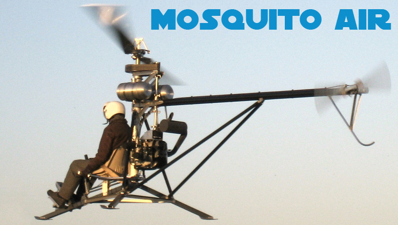
I. DRIVE SYSTEM
1. Gear Box Mounts
-
Cut and bevel three 1-1/8″ long keys from the 3/16″ keystock (V-26) and bevel the edges. Insert the keys on the top and bottom of the splitter gear box (A-01) and install the 20 mm bore coupling flanges (23-07) so that they are flush with the ends of the shaft.
-
Grease the inside of the coupling (24-11) at the front of the tail rotor drive shaft in the tail boom. Turn the coupling so that the keyway is at the bottom and insert the key. Align the gear box so that the oil plug is on the lower side of the housing and the keyway matches the drive shaft.
-
Insert the gear box into the drive shaft coupling and into the tail boom until the bolt holes line up. Place threadlocker on the end threads and insert 1/4 x 3/4 standard bolts into the top and bottom holes and 1/4 x 1-1/2 standard bolts into the side holes.
-
Place a small (approximately 10 lb) weight on the front pad. Install a key and the tail rotor gear box (A-02) into the rear end of the tail boom with the tail rotor shaft pointing to the left.
-
Thread in 1/4 x 3/4″ bolts to the top and bottom holes. Insert 1/4 x 3/4″ bolts through the tail rotor guard braces (16-09) and thread into the side holes. Use an AN4-6A bolt to mount the tail rotor guard (16-10) to its bracket and an AN4-7A bolt to attach the braces to the guard. Tighten all bolts.
2. Secondary Reduction
-
Install the sprocket flanges (25-06) on sprocket #3 (25-04) using 6-32 x 1/2 flat heat cap screws. Use threadlocker on each of the screws.
-
Remove the lower sprocket #3 bearing housing (25-02) from the supports on the main mast. Install the bearing retainer (25-10) onto the bottom using AN3-11A bolts. Do not use a washer the head of the bolt, only the nut. Do not tighten yet.
-
Press the sprocket bearing (B-03) into the housing. Finish tightening the bolts turning the nut and not the head. Install the second bearing (B-03) in the upper housing (25-0. Press the lower housing bearing onto the long end of sprocket #3 (25-04) and the upper on the short end as shown in the drawings.
-
Insert the spacer blocks (25-03) between the housings and bolt in place using 1/4 x 5 bolts. Spin the sprocket to be sure all components are in alignment and the bearings rotate smoothly.
-
Place a drop of threadlocker on the end threads of a 3” threaded rod (49-03) and thread into the hole in the edge of the lower housing. Thread a locknut up to the housing and tighten. Reverse thread a second locknut up to the first.
-
Install the sprocket assembly back on the sprocket supports with the threaded rod in the hole in the bent portion of the sprocket support brace plate (13-05). The mounting bolts should be snug but not tight.
-
Place the cog belts (V-23) around the sprockets. Tighten the nut of the threaded rod to tension the belts slightly. Rotate the rotor shaft a few times to allow the belts to align. Continue tightening until the belts deflect approx. 3/8″ with a 10 lb force between the sprockets. Finish tightening the mounting bolts.
3. Drive Shafts
-
Place a thin curved washer from the flex pack package (V-24) on each of the coupling holes on the primary reduction with the curved side facing up. Place a flex pack on top of the washer followed by a set of thicker curved washers with the curved face facing downward. Install bolts, flat washers and locknuts and tighten until snug but not tight.
-
Place a second set of thin curved washers on the open holes in the flex pack with the curved side facing down. Place the lower drive shaft (24-06) on the washers. Insert bolts through the holes and add a set of thicker washers on the bolts with the curved side facing up. Install nuts and washers on the bolts and tighten until snug but not tight.
-
Repeat this procedure for the upper flex pack and for the upper drive shaft. The thinner washer is always mounted between the flex pack and the coupling/driveshaft. The flex pack always has the curved side of the washer next to it.
-
Check to see that all the flex packs are flat. If they are being axially pulled out of their relaxed state slide the couplings on the splitter gear box up or down until they are flat. Tighten the flex pack bolts and the set screws on all couplings.
J. MAIN ROTOR
1. Blade Assembly
-
Place gap filler on the shank of an 10-32 x 2″ long screw and install in the outermost hole (closest to the blade tip) at the root end of the blade. This screw will be used for fine tune balancing weights. Repeat this procedure using AN3-12A bolts for the next two holes. Repeat for the 1/4″ hole using an AN4-12A bolt. Repeat for the second blade.
-
Ensure the inside of the blades are clean and free of any small particles. Obtain the section of 1-1/2″ thick blue styrofoam (V-03) and press one side up against the tip of the blade so the tip makes an impression in the foam. Use a sharp utility knife to cut the shape out. Test the insert in the blade tip to be sure of a good fit. Trim as required to make a snug but not an excessively tight fit.
-
Use Bulldog premium glue (V-07) to glue the inside of the first inch of the blade tip and spread on the bonding surfaces of the foam as well.
-
Insert into the blade tip until approx. 1/8″ is left protruding from the tip of the blade. Repeat for the root end of the blade and for both ends of the second blade.
-
Clean up all excess glue using a mild solvent if required (without letting it touch the foam. After the glue has cured overnight use a sharp utility knife to trim the foam flush with the end of the blade using the end of the blade as a guide for the knife to produce a clean finished look.
2. Rotor Head Assembly
-
Rotor head assembly must be done on a clean surface such as a clean piece of cloth. Be sure all parts and bearing surfaces are clean and free of contaminants prior to assembly.
-
While supporting the feather pin (not feather block) press the inner feather pin spacer (32-11) onto the feather pin protruding from one of the feather block assemblies (A-04). Press the outer feather pin spacer (32-12) onto the feather pin protruding from the other side of the block while supporting the pin from the opposite side. Press the outer feather bearing race (B-07) onto this same pin.
-
Place the inner feather bearing seal (V-63) over the ring of the inner feather pin spacer (32-11). While supporting the feather block, press the cone of the inner feather bearing (B-08) onto the spacer. Install a washer and nut to secure the inner spacer in place. Do not over tighten as this may start to pull the pin through the block.
-
Press the cup of the inner feather bearing (B-08) into an inner pivot block (33-02). Ensure the cup and cone are clean and greased. Place the pivot block and cup onto the cone while pressing the seal into place in the block until it is fully seated. Thread the grease nipple (V-66) into the 1/4-28 hole in the back of the inner pivot block. The nipple should be on the lower half of the block and point down and to the side when the block is in its final position.
-
Place the thicker (.062″) of the thrust bearing washers (B-09A) over the outer feather pin spacer followed by the thrust bearing (B-09C) and the thinner (.032″) thrust bearing washer. Be sure washers and bearing are clean and greased prior to assembly. Place the outer thrust bearing seal (32-16) over the bearing assembly.
-
Press an outer feather bearing (B-06) into an outer pivot block (33-01). Ensure the bearing and race are both clean and greased. Slide the outer pivot block onto the bearing race. Place a U-cup seal (V-62) onto the feather pin with the lips of the seal facing the bearing. Install the bevelled AN365-720 nut (V-65) onto the pin (no washer) to hold the seal in place and tighten. Repeat the above assembly for the second feather block.
-
Using AN5-11A bolts, loosely bolt a pitch horn (34-02) to the upper blade grip (32-02) as shown in the drawings. Bolt the blade stop (34-01) to the lower blade grip (32-03) in the same manner.
-
Using AN4-7A bolts with lock washers and threadlocker, bolt the upper and lower lead-lag adjustment blocks (32-05, 32-06) to their respective grips as shown in the drawings.
-
Reverse thread nuts on eight modified AN3-15A bolts with threads up to the head. Thread into the adjustment blocks until the screw is flush with the inside of the slotted hole in the block.
-
Using AN6-46A bolts through the inner pivot and AN5-41A bolts through the outer pivot, bolt the grips to the pivot blocks as shown in the drawings. The AN5-41A bolts should have AN960-516 (thick) washers under the head and nut. The threaded holes in the side of the outer pivot block should face in the direction of rotor rotation. Repeat the above procedure for the opposite grip assembly.
-
Press the teeter bearings (B-05) into the hub plates (32-01) so that they are flush with the plate on one side. Place a lock and plain washer and threadlocker on the threads of each of four 7/16 x 1-3/4 bolts. Bolt both feather blocks to one hub plate so that the bearing in the hub plate is protruding to the outside of the plate. When each of the bolts are 1/2″ from being seated, place a small amount of gap filler on the bolt shank before threading in the rest of the way. Tighten to 70 ft-lbs. Do not install the second hub plate yet.
-
Loosen the 5/16″ bolts on the outer pivot blocks. Place the lower blade spacer (32-14) over the inner hole in the bottom grip and slide the blade between the grips. Slide the upper spacer (32-13) between the blade and the upper grip. Line up the spacers and blade in the inner hole with a screwdriver and insert the AN7-42A blade bolt with AN960-716 (thick) washers under the head. Tighten a nut in place with a thick washer underneath. Repeat for the outer bolt.
-
Place the backing bar (34-07) over the holes in the outer pivot block as shown in the drawings and install 8-32×1 1/4 cap screws.
-
Place the pretensioner (34-08) on the bottom surface leading edge of the blade as shown in the drawings and dimple the blade using a 1/4″ bit. Finish drilling straight up through the blade using a 7/32″ bit and tap with a 1/4-28 tap.
-
Install the pretensioner with 1/4-28 x 3/4 bolts. Reverse thread a nut onto a 1/4 x 1 bolt and install into the pretensioner threads. Do not tighten yet. – Repeat for the opposite end of the rotor head.
2. Mounting
-
Ensure the teeter bearings and their races are clean and greased. Carefully lift and place the rotor assembly onto one of the teeter pins. Place the second hub plate on the opposite pin with the bearing protruding to the outside. Thread the 7/16 feather block bolts through the hub plate into the feather blocks as was done with the first hub plate using gap filler as described earlier but do not tighten. Complete the next step before the filler cures.
-
Slide the hub plate stiffeners (34-06) between the hub plates and install AN4-47A bolts in place to secure the stiffeners. Tighten the 7/16″ feather block bolts to 50 ft-lbs.
-
Place the teeter thrust spacer (32-10) over the protruding teeter bearing. Ensure the thrust bearings and washers are clean and greased. Install a .062″ teeter thrust washer (B-09A) over the spacer followed by a .032″ washer (B-09B) followed by the thrust bearing (B-09C) and another .062″ washer (B-09A). Install a large 1/2″ washer (V-64) over the teeter pin followed by an AN310-8 castle nut. Repeat for the opposite teeter pin. Leave the nuts completely loose so no pressure is placed on the thrust washers until after balancing.
-
Assemble the pitch links (50-03) by reverse threading nuts on 4 rod ends (B-16) with 3/4″ protruding and threading into the pitch links.
-
Bolt the pitch links into place in the butterfly levers using AN4-11A bolts. Do not bolt the links to the pitch horns until after balancing.
3. Balancing
-
Tighten the blade bolts to 50 ft-lbs. Screw in the lead-lag screws until they contact the blade bolt. Once all are in contact, tighten each screw an additional 1/8 turn. Loosen the outer blade bolt 1/2 turn.
-
Lay a 4 ft or longer straight edge along the leading edge side of the upper grip and mark with a pencil on the blade the point at which the outer end of the straight edge touches the top of the blade.
-
Adjust the lead lag screws by backing off both the upper and lower screw on one side the same amount (start with 1/6 turn each or one flat) and then turning in both screws on the other side in until tight. Make adjustments and recheck with the straight edge and pencil until the pencil mark is .625″ back from the leading edge of the blade as measured by placing a square on the flat underside of the blade.
-
Tighten the bolt in the pretensioner to 36 inch-pounds (3 ft-lb). Recheck the position of blades as outlined above and adjust the lead/lag screws as required to bring the marks back to .625″ from the leading edge of the blade. This will leave the blades in approximate lead-lag alignment and will be refined later on.
-
Ensure the digital level is correctly calibrated. Ensure the teeter pin nuts are loose and that there is nothing else that will inhibit teeter movement of the rotor. There should be no air movement in the room.
-
Place the digital level on top of the flat on top of the hub plate so that it its centered on the plate. If the level itself does not have a smooth flat bottom or is made of plastic a small section of angle or flat bar may need to be placed under the level.
-
Wait until the blades stop moving and check the reading of the level. If the blades are disturbed slightly they should return to this same reading. If this is not the case something is resisting the blade movement and the balancing will not be correct.
-
If the level does not provide a 0.0 degree reading within 0.1 degree then the blades will need to be balanced. Each degree that the blades are out of level requires roughly a 1/2″ deep 7/16″ diameter hole drilled in the end of the spar.
-
Support the heavy blade so that it cannot move while drilling. Use a 5/32″ drill bit to drill straight into the end of the spar to about 3/4 of the calculated depth at the outer end of the heavy blade. The hole should be 3/4″ back from the leading edge of the spar (not skin) and 1/4″ up from the bottom of the spar. Follow this with a 7/16″ bit. Recheck the level. Drill deeper as required until the blades are level.
-
Cut a small 1/2 x 1/2 x 1 long block of foam from the section of blue styrofoam and glue it into the balancing hole leaving a small amount protruding. After the glue dries trim the foam flush with the blade end using a sharp utility knife.
-
Once the blades are balanced tighten the teeter pin nuts and fasten the pitch links to the pitch horns using AN4-11A bolts and the pitch horn spacer (32-09). Ensure there is full rotational play in the pitchlinks after tightening the rod end lock nuts similar to what was done with the control tubes in the controls section.
K. TAIL ROTOR
1. Control Assembly
-
Press the tail rotor control bearing (B-13) into its housing (51-04) so that it is flush. Use AN3-6A bolts to hold the bearing in place.
-
Press the control bearing mount (51-05) through the bearing with the large diameter of the mount on the same side as the nuts. Press the actuator (51-07) onto the section of the bearing mount protruding through the bearing. Drill through the 3/16 holes and debur the holes inside the bearing mount.
-
Reverse thread nuts onto two 3/16″ rod ends with 5/8″ protruding and insert into the control bearing housing. The rod end housings should be parallel and facing each other as shown in the drawings.
-
Remove the two 1-3/4” bolts loosely installed on the tail boom side of the tail rotor gear box next to the tail rotor shaft. Insert the bolts through the lever mount (51-02) and the spacers (51-10) and after adding some threadlocker reinstall in the gear box. There should be a thick (.062”) washer and a lock washer on each bolt.
-
Reverse thread two nuts on two 3/16″ rod ends with 5/8″ of threads protruding. Mount on the lever mount with the housings parallel and facing each other but do not tighten.
-
Place a drop of threadlocker on a 10-32 x 1 cap screw. Insert through the tail rotor control lever (51-01) and thread into the slave lever (51-06). Place the lever assembly on the rod ends. Bolt in place with an AN3-12A bolt on top and an AN3-11A bolt on the bottom. Tighten the rod end nuts and ensure that the lever can swing freely.
-
Reverse thread nuts on two 1/4″ rod ends with 5/8″ of thread protruding. Place threadlocker on the threads and thread into the end of the slave lever with the housings parallel and facing each other.
-
Slide the control bearing assembly onto the tail rotor shaft. Insert the linkage (51-03) between the rod ends on the slave lever and on the control bearing housing (51-04). If required, bend the linkage plate slightly until it slides easily between the rod ends with no slack. Fasten in place with AN4-7A bolts on the pivot and AN3-6A bolts on the housing.
-
Slide the control bearing assembly back until the keyway in the tail rotor shaft is exposed. Insert the key (51-08) with the rounded side facing up. Slide the assembly back over the key and line up with the holes in the actuator. Grind one 10-32 x 1/2 cap screw to .400″ long. Add threadlocker and to this screw and to a 1/2″ screw and thread into the key.
-
Check the motion of the control. It should be smooth and easy to actuate with the control lever. If this is not the case check all rod ends for correct alignment and check the keyway by loosening the bolts to see if it is binding. File the edges of the key as required to eliminate binding.
-
To install the tail rotor control cable (V-04) first pull the rubber on the swivel joint forward and turn the nut off the threads and slide next to the rubber. Slide the sleeve portion of the cable fitting through the slot in the rear cable bracket on the tail boom and slide into place in the hole. Tighten the nut at the midpoint of the threads and slide the rubber back into place.
-
Run the front of the cable under the right main mast strut and through the seat supports down to the front cable bracket (16-01) and install the fitting in the same manner. Reverse thread a nut on each cable end with 5/8″ of thread protruding and thread on female rod ends.
-
Attach the rod end to the foot pedal with an AN3-13A bolt and a spacer (46-07) between the rod end and the lever. Attach the rod end to the tail rotor control lever with an AN3-7A bolt.
-
Use tie-wraps at 1-1/2 foot spacings to secure the tail rotor cable along the full length of its path.
2. Rotor Assembly
-
Use the foam and glue provided to install plugs in both ends of both tail rotor blades in the same manner as was done with the main rotor blades.
-
Rotor assembly must be done on a clean surface. Ensure the tail rotor thrust bearing washers and bearing are clean and greased. Insert a thrust bearing washer (B-12A) into the deeper hole on the end of the tail rotor feather block (33-08). Grease the thrust bearing (B-12B) and place on top followed by the second thrust washer.
-
Place a small mount of gap filler around the inner diameter of the hole above the thrust washer and press a feather bearing (B-11) over the thrust bearing until it lightly contacts the thrust bearing. Check the assembly for ease and smoothness of rotation to ensure it has not been pushed in too hard. If this is the case the bearings must be pressed out and reassembled.
-
Press a second feather bearing (B-11) into the other end of the housing while supporting the opposite end on the housing and not the bearings. Repeat the procedure for the second housing.
-
Press the tail rotor teeter bearings (B-10) into the rotor hub (33-07).
-
Insert the AN3-21A bolts into the outer tail rotor hub plate (33-05). Place the rotor hub onto the center bolts such that when the hub plate is vertical and you are facing it from the hub side (with the threaded end of the bolts pointed at you) the teeter bolt inserted through the teeter bearings would go from the top left down to the lower right. This alignment must be correct.
-
There is a 1.25 degree coning angle incorporated into the feather blocks. This can be seen by looking at the ends of the blocks. The bearings will be closer to one side than the other. It is very important that when you install the feather blocks onto the hub bolts that the outside bearing be closest to the shaft side of the hub, or next to the hub plate with the hole in it (33-06). The thrust washer end of the feather block should be next to the rotor hub (33-07).
-
Place the inner tail rotor hub plate (33-06) onto the bolts with the slot lined up with the slot in the hub and tighten on nuts.
-
Insert the tail rotor blades into the feather bearings and thread on AN310-6 castle nuts. Tighten the nuts until the blades pivot smoothly and easily with no slack left in the bearings. Insert cotter pins (V-08) into the holes in the blade pivot.
3. Balancing
-
Obtain a short (approximately 18″) section of 1/4″ rod. Insert the rod into the vice so that it is horizontal with approximately 1 foot of rod pointing out to one side.
-
Place the tail rotor on the rod with the rod inserted through the teeter bearings. You may need to reposition the rod tilting it up slightly to account for the bend in the rod under the weight of the rotor. The assembly should be level with the blades positioned horizontally and facing opposite directions as they will be when mounted on the helicopter.
-
Release the rotor. If it does not move, lightly tap the balancing rod with a small metal object to reduce any friction effects. If there is little or no movement the rotor is balanced. If it tilts, place two 3/16″ washers next to the outer most pitch horn mounting bolt on the lighter blade. Set the rotor level and recheck. Add/remove washers to the lighter blade until it no longer moves.
-
Add the washers to the outer bolt. If a longer bolt is needed remove one washer to account for the heavier bolt and install the longer bolt and remaining washers. Recheck the balance and make further adjustments if required.
4. Mounting
-
Place a small amount of grease on the tail rotor teeter spacers (33-11) and place on the teeter bearings inside the rotor hub. The grease will help to hold the spacers in place while installing the rotor.
-
Rotate the tail rotor shaft so the rotor mount hole is horizontal and slide the rotor hub over the shaft. Place a hub spacer (33-11) on the AN5-20A teeter bolt and insert through the bearings and shaft. Install a nut with no washers on the bolt and tighten.
-
Reverse thread two nuts on 3/16″ rod ends (B-14) with 1/2″ of threads protruding. Thread the male rod ends into two female rod ends (B-15).
-
Place threadlocker on two 10-32 x 1-1/4 cap screws and install the female rod ends onto actuator (51-07) with a spacer (51-11) between the rod ends and the actuator. Repeat for the male rod ends mounting onto the pitch horns with spacers installed under the rod ends.
-
Check the travel of the pedals relative to the travel of the tail rotor control bearing. A comfortable range of foot travel should send the control bearing from one stop to the other. Make adjustments to the cable bulkhead nuts as required.
L. INSTRUMENT PANEL
-
Draw a line across the instrument panel brackets (15-02) at 1/2″ up from the angle corner. Clamp to the panel (15-01) with the line on the bottom edge of the panel and centered on the holes in the panel and drill out and rivet. Ensure the bottom of the panel brackets are flush before drilling the rivet holes in the second bracket.
-
Place the panel on the front leg in the location shown in the drawings. Center the panel on the leg and scribe the location of the holes in the brackets on the legs. Remove the panel and drill out the holes with a 3/16″ bit. Mount the panel to the leg with 3/16×14 rivets.
-
Cut back the side lugs on the Tiny Tach (which will not fit through the rectangular hole on the panel) 1/8″ from the face. Push the tach into place in the square hole and fasten with 10-32 x 1″ cap screws. The face of the Tiny Tach should be flush with the face of the panel.
-
Mount the air speed indicator in the next hole above the Tiny Tach. Drill out the mounting screw holes and fasten in place with the screws in the package. Mount the quad CHT/EGT in the next hole up and the Rotor/Engine Tachometer in the top hole following directions provided with the instruments.
-
Mount the pitot tube on the side of the foot pedal lever support with 3/8″ clips. It should point approximately 10 degrees up from level as the helicopter points down slightly when flying at speed. Drill a 1/4″ hole just behind the foot pedal support in the top-center of the leg. Cut the small 1/4″ black pitot tube transition sleeve in half and cut a 3″ and a 5″ section of clear tube.
-
Use the transition to connect the pitot tube to the ASI as shown in the vendor assembly drawing. Use the other section of transition to connect the static port into the front leg to provide a “dead air space” as required for the correct operation of the ASI.
-
Drill 3/16″ holes just before the “Y” in each exhaust manifold and use the clamps to mount the EGT senders. Place the CHT senders under the upper spark plug on each cylinder. Route the four wires together on the left side of the main mast and connect to the proper terminals on the gauge.
-
Run the wire from the “Tiny Tach” next to the gauge wires up to the bottom spark plug wire on the engine. Wrap the red tach wire around the spark plug wire 4 times and tape in place. Use the grounding bolt on the lower left side of the engine to mount the ground wire.
-
Follow the directions in the rotor/engine gauge to mount the rotor and engine senders as required. Route wiring along with the other wires from the engine.
-
Drill a 1/2″ hole in the front face of the left and right seat supports about 3″ down and 1″ in from the edge and install the engine master and start switches. Wire the switches as shown in the wiring schematic provided and solder and tape all connections.
-
Enclose all wires together in the 5/8″ loom (V-10) provided and use tie wraps to secure in place.
III ROTOR TUNING
A. Main Rotor Static Pitch
-
Place a small punch mark on the tip of one of the blades in the end of the spar about 1/4″ from the leading edge. Place another punch mark on the leading edge of the same blade about 1/4″ from the root. This will be designated as blade number one.
-
Use a bungee cord to strap the cyclic stick back to the center of the front of the seat. Stand directly in front of the front pad and press the digital level to the underside of the flat spar portion of blade. Adjust the pitch link by unfastening the lower pitch link bolt and turning the rod end in or out as required.
-
Adjust as required to bring the level to 0 degrees +/- 0.1 degree. Each 1/2 turn of one rod end represents approximately 0.2 degrees of pitch. Move the rod ends at both ends of the pitch link in or out approximately the same amount. After refastening ensure the rod ends at each end of the pitch link are in line with each other to permit the link to pivot on its axis the maximum amount possible.
-
Smoothly swing the blades around so as not to move the cyclic stick and standing in the same spot adjust the number 2 blade until it has the same reading as blade 1. Recheck both blades. Remove the bungee cord.
B. Tail Rotor Static Pitch
-
Rotate the tail rotor until the blades are horizontal. Adjust the foot pedal until the control hits the full right stop (right pedal down). Hold the rotor so that it is perpendicular to the tail rotor shaft. Hold the digital level alongside the center of the tip to the to the center of the trailing edge of the blade to measure the angle of the blade. Adjust the pitch link until this reads 87 degrees +/- 0.5 degree.
-
Rotate the rotor 1/2 turn and repeat with the second blade. Adjust the pitch link as required until the second blade has the same reading. Recheck both blades.
C. Main Rotor Balance
-
Start the engine and proceed through break-in steps as required. When full rpm operation is permitted rotor tuning can continue. If the rotor can be brought up to full speed with minimal vibration engine break-in can be completed. If not, final rotor balancing will need to be completed at lower rpm’s until the rotor is adequately balanced for full speed operation.
-
The following procedure is for tuning without an electronic balancer. If you are able to obtain a balancer you should follow the directions provided with the balancer for the most accurate tuning.
-
Run the rotor up to full speed of 500 rpm (or a lesser speed if vibration becomes uncomfortable) for the first time and feel the vibration produced by the main rotor. Shut down the engine and wait until the rotor stops. Loosen the outer blade bolt on blade #1 1/2 of a turn.
-
Back off the locknuts on the adjustment screws two turns each and position so that the flats of the nuts on the sides are vertical. Use the nuts for rotation reference points. Back off the two front screws “one flat” each ie. turn out each screw 1/6 of a turn (until the next flat is vertical). Turn in the two rear screws until tight (approximately the same amount). This will pivot the blade forward slightly. Retighten the outer blade bolt.
-
Bring the speed back up to 500 rpm (or the same max rpm achieved previously) and feel the vibration. If it is better or no different than the first attempt repeat the above procedure. If it feels worse turn the screws back to their original position and then another flat beyond that. Recheck the vibration.
-
Continue with the trial and error method continuing in the direction that reduces vibration until it begins to increase again. When in the area of least vibration move the screws only 1/12 (flat to point) at a time to bring the vibration down as low as possible.
-
At this point there should be virtually no main rotor vibration left. If there is still vibration it is due to rotor imbalance. Add four standard 1/4″ SAE washers to the 2″ long cap screw near the root of blade #1 and check the vibration. If it feels better change the number of washers until the vibration is eliminated. If it feels worse move the washers to the other blade and make adjustments as required.
-
When finished there should be no rotor frequency vibration left. You will always be able to feel a small amount of high frequency engine vibration but there should be no vibration from the main rotor.
D. Tail Rotor Dynamic Balance
-
Tail rotor imbalance will feel like a buzzing feeling in your back. Lower level tail rotor imbalance can be difficult to distinguish from normal engine vibration.
-
If the tail rotor feels out of balance try adjusting the number of washers on the outer blade fastening bolt (same as used for the static balance) and using trial and error as was done with the main rotor to reduce the imbalance as much as possible.
E. Dynamic Pitch Trim
-
As you are bringing the engine up to approx. 2000 rpm observe the tips of the blades passing in front of the helicopter. If they are pitched correctly they will both follow the same path. If they are out of adjustment the tips will appear to oscillate up and down as each blade passes in its own path.
-
If they are out of adjustment adjust the pitch link on blade #1 by turning the lower ball joint in 1/2 turn. Recheck the tip paths. If they are closer to being in line then turn the pitch link on blade #2 out 1/2 turn to keep the nominal setting of the blades the same for autorotation purposes. Continue in this manner until both blades are in the same path.
-
If they are further apart turn the link on blade #1 back out to its original position and out a further 1/2 turn and recheck. Make further adjustments as required to each blade until the blades are in line. The helicopter is now ready for hover trials.
-
Final pitch adjustments must be made during forward flight. With the helicopter in forward flight at approx. 50 mph notice if there are any “1 per rev” oscillations similar to out of balance vibration. This is caused by pitch trim.
-
After taking a short flight land the helicopter and adjust the link on blade #1 up 1/2 turn. Take another short flight and check the vibration level. Adjust the link up or down as required until the vibration is minimized.


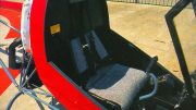
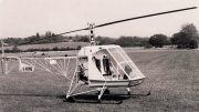
Hello, the assembly manual is very interesting, but I would like to know if there is any possibility of getting the sheets with the drawings referenced in the manual. I contacted the current manufacturers of the new model, asking them for the possibility of having a kit, and they told me no. I think they are very busy with the new models, but I like this model, so I’m trying to get more information about the initial model, the mosquito air. Thank you very much, Jorge
We are hoping to make this information available in the future as the late John Uptigrove (the original designer) and I shared a lot of information in the very early days of his experimenting. It was noted that John had inspiration from a number of existing designs such as the mini-1 helicopter, the G-1 helicopter, and the Lonestar helicopter controls, buy the late Ken Rehler, which I now own the rights for.
Hello, I bought the Lonestar blueprints years ago, I also have the blueprints for the Cicare Fury, and the Mosquito is a concept similar to the CH4 but simplified in its construction, that’s why I like that model. Who owns the rights to that model, the Mosquito Air? Composite FX? I think I read that about 400 kits were manufactured, of which there must be some unfinished ones, I’m trying to get one of them, but I haven’t found anything yet, so I’m looking for the assembly drawings of this helicopter. Thanks for your time, regards.