

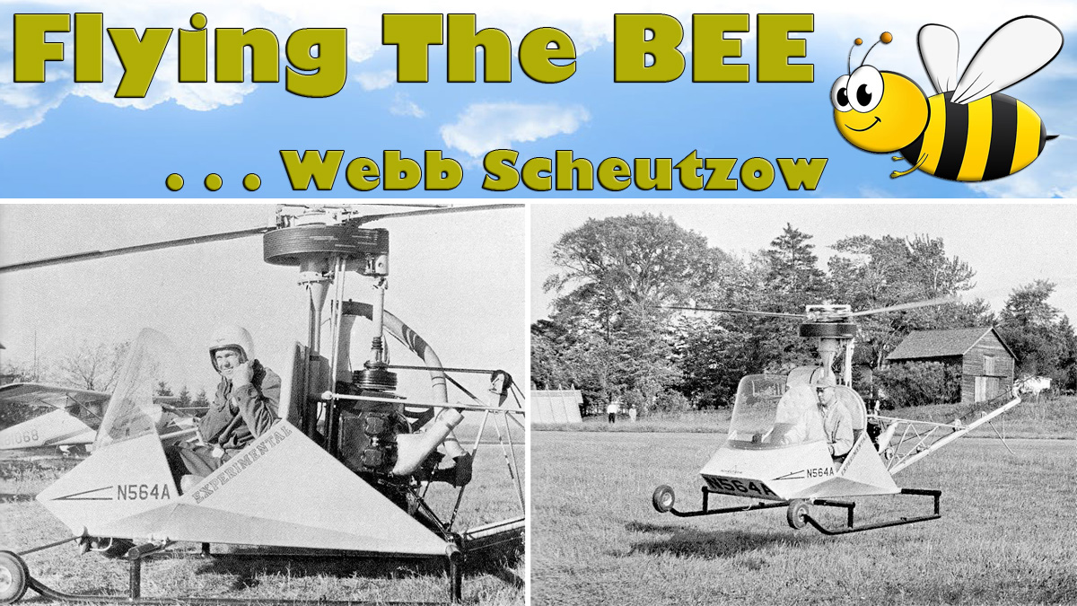
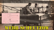
Scheutzow Bee Helicopter Gets Airborne
ARTICLE DATE: May 1974
Photos Courtesy Scheutzow Helicopter Corp.
Flying the BEE was a perfect example of utmost confidence — confidence of the pilot and builder in each other. This confidence goes back many years. Webb Scheutzow is my brother — we grew up together, and as kids we were always designing and building something. Lots of times it was model airplanes. In the winter months it’d be bob sleds.
We’d build ’em and break ’em up on the hills; take ’em home and rebuild ’em. Over a long period of time we learned each other’s capabilities, potentialities, and limitations. During the whole decade of the 1930’s we had a ringside seat for the Cleveland National Air Races. Our home was only two miles north of runway 23 at Cleveland Airport.
Within walking distance we got to see Steve Wittman, Doug Davis, Roscoe Turner, Jimmy Doolittle, Tony LeVier and others on the ground and in the air. As Jimmy Doolittle flew his Gee Bee Special over our house on speed trials we could hear his ignition clacking in the earphones of Webb’s ham radio receiver.
What I’m trying to point out here is our orientation toward the subject of flying machines. In previous articles, Webb has told you how he got interested and built the Model B. But the moment of truth and the sticky wicket eventually arrives after the designer-builder has invested untold hours and sweat in his project.
That moment can be summed up in the question: “Will it, and how will it fly?”. No doubt Stits, Smyth and Pitts all had to face up to the same momentous question after the rivets and welding torch were put away.
When Webb asked me to put his newborn Scheutzow Bee Helicopter through its paces, I had oodles of hours acquired during WW-II as a Naval Aviator flying the Piper Cub, Waco UPF-7, Stearman Primary trainer, SNV, SNJ and SNB.
My duty in the Navy was instrument flight instructor in the SNJ and twin Beech. My commercial ticket read “airplane, single and multi-engine land; flight instructor.” At the birth of the BEE I was transitioning to a rotorcraft rating with a few hours in a Brantley and the rest in a Hughes 269A — total time about 11 hours.
See what I mean about confidence? But what a contrast between walking up to an old bird and walking up to a chick with the fuzz on it yet carrying the “EXPERIMENTAL” tag! How do you find out how she wants to fly so that you can walk away from her each time?
The method we decided upon was to crawl, then walk and finally run. In other words, we’d hover her, then make short, low altitude flights and finally flights of 200 to 300 feet altitude for longer flight duration in the Scheutzow Bee Helicopter.
In order to hover, the used 85 h.p. Continental had to be over-revved slightly, then the collective brought up and she’d lift off. I dared not go too high in the air because the increased angle of attack on the blades would cause rotor RPM to decay and a hard landing would result.
The power plant was not pretested on a dyno, therefore it’s not known exactly what power was being produced. It felt like just a few more ft.-lbs. of torque and we could sustain a hover out of ground effect.
Kicking right rudder (it puts more power into main rotor) and performing a right hand turn over a spot nearly did it, but this was no big problem. In this hover phase of testing we experimented with and without the gyro-bar installed.
The difference was amazing. With the gyro-bar, the Scheutzow Bee Helicopter had the stability and inertia characteristic of a large, heavy automobile. Without the gyro-bar it felt like driving a sub-compact over a bumpy road.
This gyro-bar is built into the controls at the top of the mast and performs as a gyroscopic stabilizer in the control system. Some refined goodies were noticeably absent such as 100% co-ordinated collective-throttle linkage and a counterbalanced collective. These niceties would come along with further development.
The belt driven tail rotor was plenty responsive and proved adequate even when turning the tail boom into the wind. Forward flight from a hover was virtually impossible. There wasn’t enough time to get completely organized before the main rotor RPM decayed.
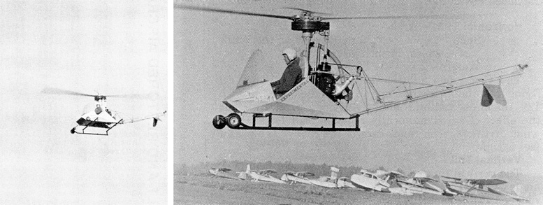
LEFT: Willis has the BEE up on a test circuit of Strongsville Airport in this photo. All of the later test flights were made using the gyro stabilizer bar, which made the helicopter much easier to fly. The gyro bar provided stability without impairing agility or controlability. Some of these design considerations will be discussed in a later articles.
RIGHT: Willis Stuart hovering at approximately “hover ceiling.” Gyro bar has been installed in this photo; also note air intake for the vertically mounted 85 HP Continental has been brought forward and up, to the top of the fuel tank to obtain lower temperature carburetor air which increased power available.
A forward leaping take-off was considered similar to jump take-offs with autogyros; but one slight miscalculation could end in disaster. The only safe and sane way to approach flying the BEE was with a running take-off and a running landing. This is a technique used for high terrain or overloaded take-offs.
The beauty of this approach is that after a short ground run (into the wind), 60% more lift is attained after going through translation. This additional lift is due to the induced airflow through the rotor system gained from forward speed.
It worked! A series of short flights at 5 to 10 feet altitude and 55 mph were attained in the Scheutzow Bee Helicopter. During this series, a minor adjustment in CG was made to take some of the forward pressure off the cyclic stick.
There were no trim mechanisms on the Scheutzow Bee Helicopter — these too would come later. After several hours were spent doing short hops, I was beginning to feel at home with the BEE. It’s a feeling like I’m part of the aircraft and like the aircraft is an extension of me.
I have learned all her idiosyncrasies and am ready to take her up. Finally on the cold morning of October 13, 1963, utilizing the running take-off and right hand turns, I climbed the BEE to 200 feet altitude and attained 70 mph circling Strongsville Airport.
The Scheutzow Bee Helicopter could fly, proving the superiority of Webb’s patented FLEXHUB rotor system. From my association with the project, I predict that the BEE will prove to be the best performing and most forgiving helicopter obtainable.
N592A SCHEUTZOW BEE HELICOPTER PRODUCTION PROTOTYPE
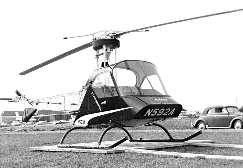
N592A PRODUCTION PROTOTYPE – “A direct descendant of the BEE Test Bed, Production Prototype N592A is shown in its original configuration, as it appeared in the spring of 1967. Many improvements resulted from our test and development program, but external appearance changed very little. We now have a total of 700 hours on two production prototypes N592A and N5182. The wood platform shown served as our airport.”
In this discussion we will describe the characteristics of the production design BEE which is now in the final stage of FAA certification under FAR 27. Some insight into the flight qualities and test requirements for helicopters in general will derive from this discussion.
The BEE was designed as a utility configuration, emphasizing simplicity, ruggedness and low cost. No effort was made to streamline the structure aft of the cabin enclosure. This type of aircraft is used for training, patrol, ranching, surveying, construction liaison and crop dusting and spraying.
The open tail boom permits maximum maneuverability in turns for crop dusting work and the exposed components can be easily inspected and maintained. Maximum speed of the small utility helicopter is usually in the 85 to 100 mph range.
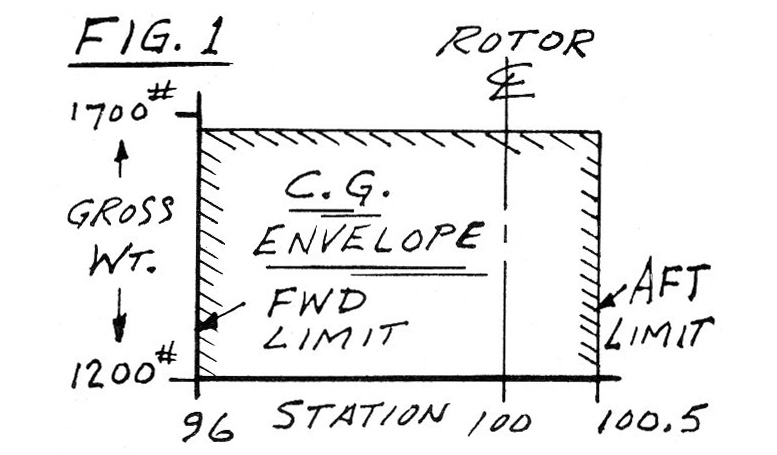
Now looking at the performance figures: Fig. 1 shows the BEE’s e.g. envelope. The datum for e.g. is arbitrarily taken as a point 100 inches forward of the rotor mast. The forward e.g. limit is at Station 96; i.e. 4 inches forward of the mast and the aft limit is Station 100.5, or one half inch aft of the mast. The e.g. range shown is fairly typical of small helicopters.
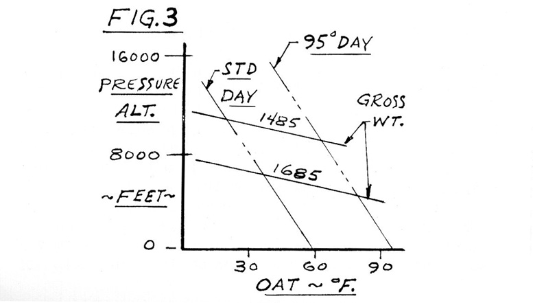
The fuel tank is located on or close to the e.g. so that fuel load is not a factor, the baggage compartment is also on the e.g., therefore only personnel and equipment loads are significant. Fig. 2 shows maximum forward speed, or Vne:-Max. allowable forward speed (IAS) diminishes with altitude usually at the rate of 2 to 2.5 mph per thousand feet.
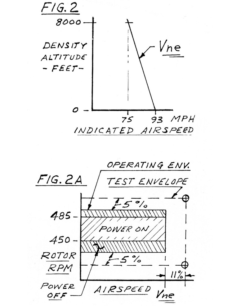
Referring to Fig. 2A you will see the flight envelope. Rotor system strain gauge data, controllability and stability must be demonstrated for all flight conditions up to speeds of 111% Vne. (Vne is 90% of the max. velocity demonstrated.) This series of tests requires investigation of rotor RPM 5% above maximum red line, and 5% below minimum red line.
Data is obtained for “power on” and “power off” flight in all maneuvers, throughout the e.g. envelope, at sea level and at 6000 ft. altitude. The BEE’s 93 mph red line is attainable in level flight at max. continuous power.
Rotor roughness in maneuvers at 111% Vne with low rotor RPM is usually the limiting factor in establishing the flight envelope. As speed is increased the rotor disc is increasingly tilted forward to obtain propulsive thrust.
As this takes place, the pitch of the advancing blade decreases relative to the flow, and the retreating blade pitch increases. At low rotor RPM and max. speed, the retreating blade will begin to stall out at the tip, causing roughness. In actual operation this is an easily discernible condition and is corrected by first reducing speed and then increasing rotor RPM.
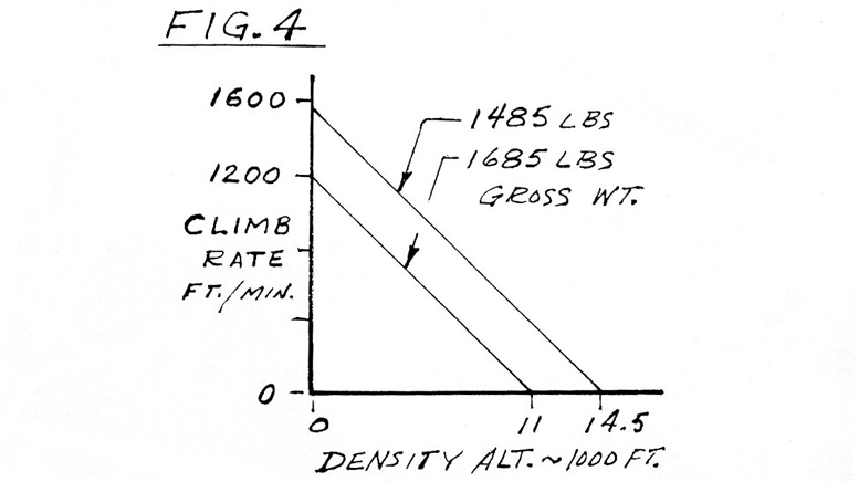
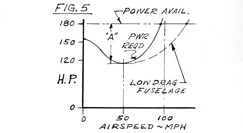
Fig. 4 shows maximum rate of climb at optimum climb speed; usually this is at about 50 mph for utility helicopters. Climb rat e derives from excess power available, above the power required for level flight. Referring to “A” in Fig. 5 you will note that at 50 mph, 62 hp is available for climb which converts to 1200 feet per minute climb rate at 1685 pounds gross weight.
Fig. 5 shows the typical helicopter power-required curve. Note that the power required at 50 mph is about 75% of the power required to hover; as the helicopter goes into forward flight the rotor picks up induced lift and it becomes more efficient. Up to about 50 mph fuselage drag is not significant. The rapidly increasing “power-required” above 50 mph is caused by drag.
The dash line on Fig. 5 shows the effect of reduced fuselage and parasitic drag on forward speed. The “bucket” in the power curve will be wider and the point at which “power required” crosses “power available” will be at a higher speed.
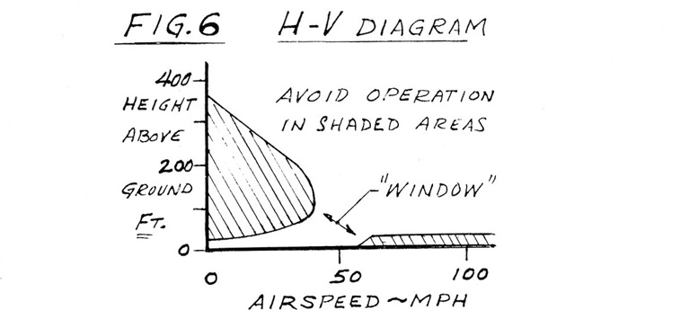
Fig. 6 shows the Height — Velocity (or H-V) diagram typical for single engine helicopters. The shaded area below 45 mph should be avoided for “personal reasons”; i.e. a safe emergency power-off landing may not be successful if you are operating within this area.
However, a major safety factor working for the single engine helicopter is it doesn’t need a 2000 foot cleared strip in the event of an emergency landing. Ground touch down is made at zero or near zero forward speed. Takeoff and landing should be made through the H-V “window.”
If you are operating inside the edges of the H-V diagram a forced landing may cause damage to the landing gear or tail boom. Factors providing for good power-off qualities are high inertia and low C/L in the main rotor.
When making the flare, just prior to touch down, main rotor RPM will rev up to the max. red line; the pilot then has a “storage battery” of inertia HP which he uses in making a collective pitch touch down. High rotor inertia puts more power into the storage battery.
Lowest rate of descent is usually close to best climb speed; power-off approaches are made at 50 to 60 mph. As with fixed wing, a clean, low drag fuselage will provide a flatter glide slope, hence a larger area from which to select a landing spot.
The small field emergency requirements of the helicopter permit operating at lower altitudes than fixed wing aircraft. Around busy airports helicopters usually operate below fixed wing traffic.
FOOTNOTE: THE SCHEUTZOW HAWK
The Scheutzow HAWK has been designed with special attention to techniques and materials for homebuilding. This new helicopter will have outstanding stability and maneuverability and something new . . . IT’S FAST!
BUILDERS TIPS: Making Hard To Guess Tube Angles For Cutting
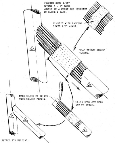
EAA member Ralph King of Silver Springs, Florida, who is building a FOO-Fighter, passed on this clever gadget for marking tube angles for cutting. Those who have tried to cut and fit tubing know that it is otherwise a trial and error exercise at best.
The item in simple terms, is a length of elastic which is sewn over a backing material length-wise every 1/8″. Wires or small welding rod is inserted between each sewn strip. After all the wires are inserted into the elastic, it is wrapped around a piece of the tubing to be fitted.
Use a rubber band to hold the marking device together. The next step is to push this item up so that the individual wires contact the structure to be fitted. After all the wires are pushed into contact, slide the whole marking gadget back.
Draw a pencil line around the contour formed by the wire tips. Use a silver pencil so that the line can be seen. Cut and file the end down to the line. The fit will please you.
Tony Bingelis
Designee Co-Chairman
UPDATE
From: Colin Hopkins
Hi, Thanks for an informative website.
I noticed you copied info from one of my Facebook posts relating To Web Scheutzow’s “Stork” helicopter. Wish I had more info to offer but most has been forgotten by anyone involved in the development of this machine.
EDITOR: actually, the information was found in an old Sport Pilot aviation magazine.
I did manage to chat with Paul Scheutzow, one of Web’s sons and he advised the drawings/sketches/prototype were sold to a guy whom he never heard of again.
There was an old black and white photo on the web with Paul sitting in the completed machine. It was a close up 45 degree frontal shot similar to the photo you displayed of the incomplete machine. I have not been able to locate it again.
I was given the printed manual by a colleague along with a couple of photos. One was a shot of Webb holding the rotor head which appeared to show the hub bar and 2 blade holder sections retained by spiral wire wrap around the 3 pieces and retained by upper and lower flanges on each section.
The blade pitch automatically increased with revs through a delta 3 arrangement where the blade grips attached to the hub bar.
Cheers
Colin
Courtesy
https://www.rotaryforum.com/forum/kit-makers-manufacturers/helicopters/1121499-scheutzow-stork
http://www.aviastar.org/helicopters_eng/scheutzow.php
https://www.facebook.com/groups/514826428669199/permalink/901207063364465/
Be the first to comment on "Test Flying The Scheutzow Bee Helicopter"