
HelicopterRotorhead Design & Function
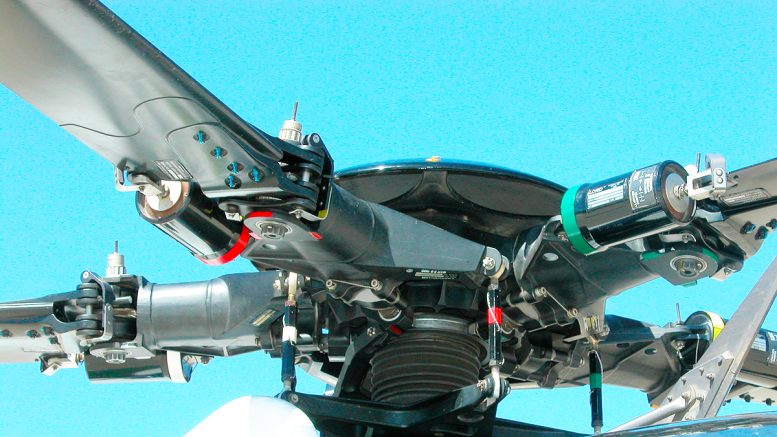
The heart of all rotorcraft, whatever the configuration, lies at the center of the rotorhead. Through the geometry of this rotating mechanical assembly, all the power and all the major control functions are passed to the helicopter rotor system while back through it, as appropriate to the helicopter rotorhead design, comes the principal response to aerodynamic effects.
All the basic helicopter rotorhead principles of aerodynamics explained here-in the first chapter of this volume apply equally to the individual blades of the rotor system; but there is added complexity of effect due to the more complex motions of the blades with respect to the fuselage. In hovering flight, each blade is generating a constant lift proportional to the square of its own rotational speed throughout its 360° cycle of rotation.
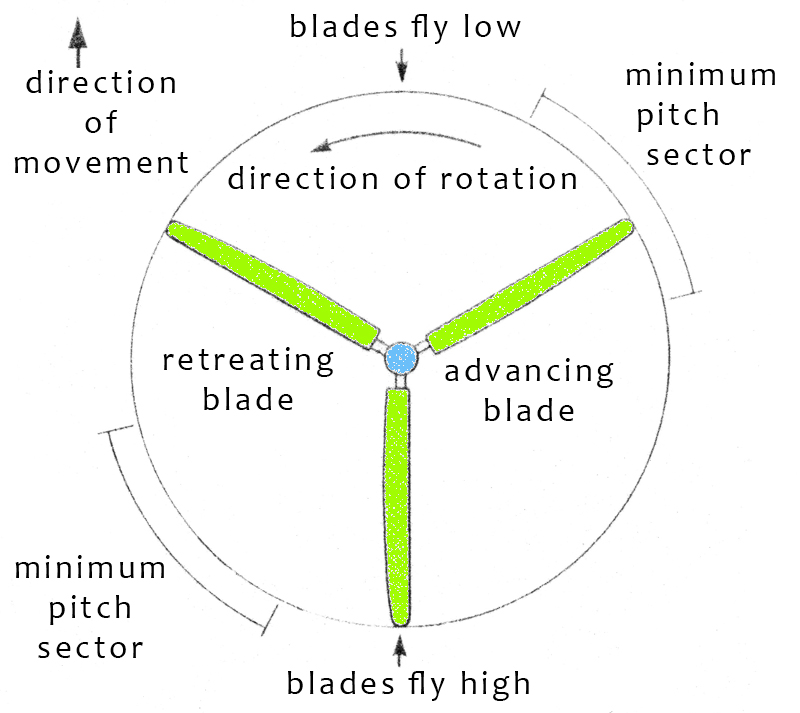
As soon as the machine begins to move forward, however, each blade produces lift proportional to the square of its rotational speed plus the forward speed on one side of the rotor and minus the forward speed as it passes round on the opposite side. The two sides are termed the advancing and retreating sides of the rotor disc.
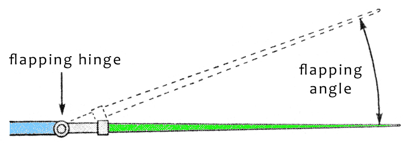
Lift asymmetry between the advancing and retreating sides, which would obviously cause lateral instability, is avoided in most helicopter rotorhead designs by the inclusion of a flapping hinge on the hub, inside the blade root attachment. This allows a blade to flap upwards in response to its increasing lift as it comes into the influence of the higher-velocity airflow on the advancing side.
This upward movement reduces the blade’s angle of attack and, consequently, its lift. The reverse occurs as it passes round to the retreating side and flaps downward again in response to the lower-velocity air, increasing angle of attack and lift. Blade lift is thus automatically equalized between the two sides of the disc.
Origins Of The Helicopter Rotorhead
In Cierva’s original autogyros, plain steel bearings were used for the flapping hinges. Later, roller bearings took their place while, in the latest helicopter designs, elastomeric bearings needing no lubrication are used. The equivalent effect in so-called rigid-rotor helicopters is achieved through the medium of a flexible section at the root end of the blade spar itself.
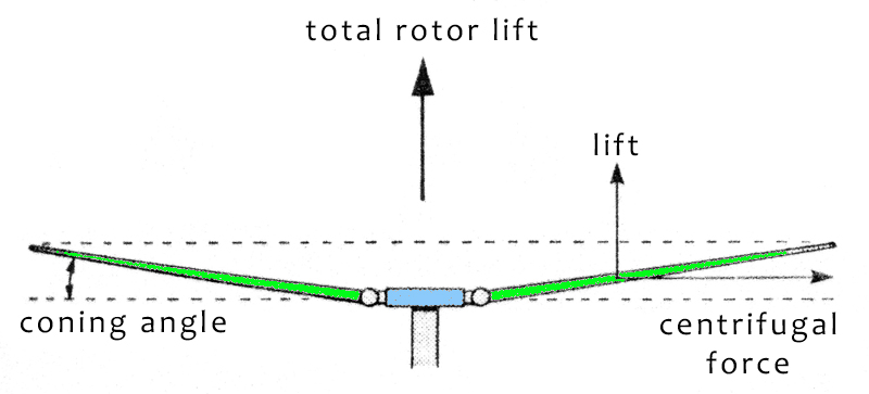
Equalization of lift over the swept area is also influenced by the rotor control system. In flight, the blades are held in position between the effects of lift and centrifugal force, the latter being approximately five or six times greater than the former.
The overall rotor lift can be taken to act through a point at the hub center and control of flight attitude is effected by means of tilting the rotor so that its overall lift vector moves away from the vertical, remaining perpendicular always to the plane of the spinning blades. The helicopter thus tilts with the rotor and then begins to move into the direction of tilt.
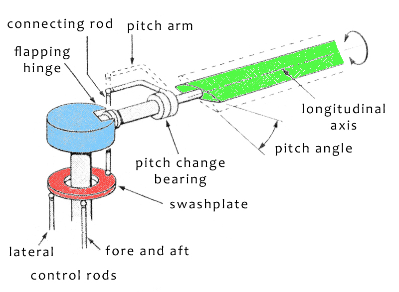
Tilting the rotor for control purposes is achieved either by mounting the hub on a universal joint and tilting it through a lever mechanism connected to the pilot’s controls, or by fitting a universally mounted swashplate below the hub which is likewise connected to the pilot’s controls.
In this case, pitch-change bearings (to allow the blades torsional freedom about their longitudinal axes) are fitted in the blade-spar roots and connecting rods link the tiltable swashplate to pitch-control arms on the blades.
In the case of the tilting-hub method, as used in the early autogyros, a forward tilt of the hub introduced by pilot control reduces the pitch
angle of the advancing blade with respect to the fuselage because it inclines the flapping hinge axis.
At the same time, the same hub inclination increases the pitch angle of the retreating blade. A forward rotor tilt thus follows the forward hub till because the blades are made to fly low in the forward sector of the disc and high at the rear.
In addition, asymmetry of lift is influenced by the input of such a control tilt because the magnitude of blade lift is dependent both on the pitch angle and on the air velocity. Since the reduction of pitch resulting from the forward hub tilt takes effect in the advancing sector of the disc, and vice versa on the retreating side, the advancing blade loses lift while the retreating blade gains lift from the effect of the hub inclination.
The flapping effect and the forward tilt effect of the helicopter rotorhead are therefore working in harmony to equalize blade lift on the advancing and retreating sides of the rotor. Although the blade pitch change introduced by the control tilt does minimize the flapping motions of the blades, the flapping hinges are nonetheless necessary as some residual flapping still occurs which would otherwise lead to undesirable blade-root stresses and vibration.
The same applies to the alternative method using the tilting swashplate, which is known as cyclic pitch control. A forward tilt of the swashplate causes the blade pitch arm connecting rods to be pulled down on the advancing side while, at the same time, they are being pushed up on the retreating side.
This reduces the pitch angle of each blade with respect to the hub when advancing and increases it again when retreating, by twisting it about its pitch-change bearing. In this case, the effect on rotor tilt is accentuated. The cyclic variation of blade pitch is in the order of 10°, from a datum setting plus 5° on the retreating side to datum minus 5° in the advancing sector.
Control movements to tilt either the swashplate or the universally mounted hub are made through a bearing assembly, since they are rotating with the rotorhead whereas the control-lever mechanism is mounted on the fuselage structure.
Use of the tilting-swashplate method also allows the introduction of what is known as collective pitch control. Its primary function is to provide for control of movement in the vertical sense at take-off and landing. Superimposed on the rotorhead cyclic pitch-control mechanism is another assembly which permits the swashplate itself to be raised or lowered, irrespective of its angle of tilt.
Thus the helicopter rotorhead connecting rods to the blade-pitch arms can also be pushed up or down in unison, either to increase or decrease the pitch angle of all blades simultaneously. Associated engine – control linkages ensure that as the connecting rods move the blade-pitch arms upwards, increased power is applied to the rotor drive-shaft, and vice versa.
This power control is often applied through the medium of an engine-speed governor, particularly with turbine-powered helicopters. The range of collective pitch control available on a typical helicopter would be from 2° positive (the autorotative pitch) to about 14° positive.
For take-off, the collective pitch lever would normally be raised to give a setting of some 10″ on the blades, at which point the machine would lift off. To sustain forward flight, a continuous forward tilt is applied to the rotor through the controls; higher speeds arc attained by increasing collective pitch and power.
In this condition, the individual blades will be changing their pitch continuously at a rate of something like eight times per second, as they pass through their cycle of rotation. In the event of engine failure, the pilot action is to reduce collective pitch to the lowest value, where upon the helicopter becomes an autogyro and glides gently downwards with the rotor in autorotation.
In the autogyro itself, blade pitch is normally fixed at the 2° setting and the rotor is not tilted forwards to provide propulsive thrust. This comes from the conventional propeller. In both the helicopter and the autogyro, lateral tilling of the rotor is used for sideways and turning control.
Reference to the section on aerodynamics will show that the reduction of blade lift resulting from its upward flapping motion is governed by the reduction in the blade’s effective angle of attack. The reduced lift following a reduction of blade pitch angle represents a different means of achieving the same objective. The difference between angle of pitch and angle of attack is explained in the glossary.
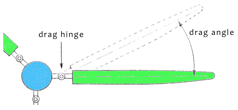
There remains one further degree of freedom which may be allowed to the blades in some helicopter rotorhead designs. This is achieved by including drag hinges, also known as lead-lag hinges, which permit the blades limited motion with respect to each other in the plane of rotation.
For a combination of aerodynamic and mechanical reasons, the blades tend to speed up very slightly as they pass through the advancing sector of the disc and slow down again they traverse the retreating sector. These minor accelerations and decelerations within the spinning rotor would give rise to vibrations if not suitably suppressed.
Drag hinges are normally located between the flapping hinges and pitch-change bearings, but in some cases the flapping and drag hinges are coincident. Some designs dispense with drag hinges in favor of providing suitable stiffness in the blade spars themselves.
Rotors fitted to the helicopter rotorhead with both flapping and drag hinges are known as fully articulated since the combination of the two constitutes the equivalent of a universal joint. Rotors with flapping hinges only are termed semi-articulated.
The addition of hydraulically operated servo controls, in the larger helicopters, does not necessarily affect the geometry of the rotorhead, but other design refinements may do so.
For example, if the flapping-hinge axis is designed to be set at an angle of less than 90° to the blade’s longitudinal axis, when the blade flaps upwards the motion will also have in it an element of pitch reduction.
The so-called rigid-rotor helicopters, which at the time of writing comprise only a small proportion of all rotorcraft, would be better described as hingeless-rotor machines. They function on much the same principles, using flexible members in place of hinges in order to reduce complexity of the expensive helicopter rotorhead.


Be the first to comment on "Helicopter Rotorhead Design & Function"