
The Wing Of A Helicopter
rotor blades and their construction
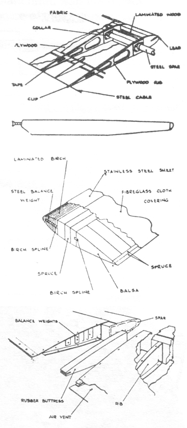
The rotor blades used by the early Sikorsky and Piasecki helicopters were derived from those that had been developed for autogiros. Figure 1 shows the construction of these rotor blades. The main structural member was the steel tube spar to which ribs were attached using metal collars.
These were bonded to the spars with a special adhesive; spot welding or riveting was not allowed since they led to early fatigue cracking of the spar. The spar ended in a fitting at the blade root which was attached to the hub by flapping and drag hinges used to reduce root end stresses.
Weights were placed in the blade leading edge to bring the chordwise center of gravity (CG) to the 1/4 chord point (also the location of the spar) or slightly ahead. This was done to prevent flutter, the blades being relatively soft in torsion. Symmetrical airfoils (e.g. NACA 0012) were used because they had zero aerodynamic pitching moment.
With an unpowered control system blade pitching moments are fed back into the cyclic control stick as steady and shaking forces. Zero aerodynamic moment reduces the shaking forces.
On the steel tube type rotor blades, with its plywood and fabric covering, the airfoil surface was not smooth and it distorted in flight causing higher drag than with a smooth airfoil surface. Also, blade manufacture required a large number of man-hours. To overcome these deficiencies Sikorsky developed the all-metal blade; more on this later.
Bell Helicopter’s two-bladed teetering rotor design used an all wood blade similar in construction to that of Figure 2. These blades had good airfoil quality, but suffered from the tendency to absorb moisture which could lead to rotor unbalance. As in the steel spar blade, the airfoil was symmetrical and the chord-wise CG was near the 1/4 chord position.
The Air and Space (Crown) autogiro used a similar blade construction. While wooden blades are heavier than the steel tube spar blades, heavier blades have an advantage in autorotation particularly during the landing flare (higher stored kinetic energy).
Sikorsky’s all-metal blade consists of an extruded aluminum alloy “D” – shaped spar, which occupies 40% of the chord, and a light-weight aft portion made up of segments called “pockets”. Figure 3 shows the blade construction.
Each pocket was about one foot long on an H-19 (S-55) helicopter, and built up of magnesium sheet with a rib at each end and a trailing edge strip. The pockets were bonded to the spar with a special glue. Each pocket was separate; no continuous trailing edge strip was used.
This permitted chordwise flexing of the rotor blades without putting compression-tension load on the trailing edge, thus reducing blade weight. Air flow between the pockets was stopped by light-weight foam separators. As with other rotor blade designs, chordwise balance was around the 1/4 chord point. Because of the extruded spar, the blades used a rectangular planform and a constant airfoil shape from root to tip. Blade twist was incorporated easily and was used to improve rotor hover efficiency and forward flight speed.
Unlike steel, aiuminum alloy has a finite fatigue life. Initially. Sikorsky took a cut-and-try approach to extending the usable operating hours of the blades, removing blades at a set number of hours and continuing testing in the laboratory.
This cumbersome process was eliminated by a brilliant invention, called the Blade Inspection Method (BIM) system in which the D spar was sealed at both ends and a gas (nitrogen) put in under a few pounds/sq in pressure. A pressure gauge attached at each blade’s root end showed any pressure loss. Even a small crack in the spar would lead to pressure loss and the blade would then be removed.
Cracks propagate slowly and there is no danger of catastrophic failure after a crack is detected. The BIM system led to a great extension in operating hours for the blades, allowing them to be retired “on condition” and not at any set number of hours. There are other metal blade designs in use which do not use the Sikorsky approach.
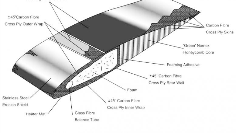
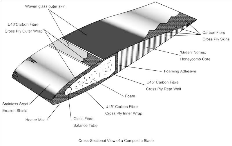
The advent of composite materials has revolutionized the design and manufacture of rotor blades. These new blades now are made completely of composite materials, except for the leading edge weight.
Fiberglass and graphite are laminated together using epoxy binder to form fatigue-proof (infinite life). aerodynamically efficient blades. They can be designed to have any taper, twist, airfoil section variation and weight distribution, root-to-tip, desired. Selective incorporation of graphite is used to control blade stiffness to get required structural-dynamic characteristics.
Be the first to comment on "Understanding rotor blades – the rotary wing"