
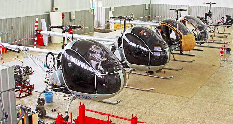
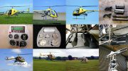
Aerokopter AK-1 Kit Built Helicopter Image Gallery
A little background on Aerokopter: With Ukraine now free of the shackles from its former master, the Soviet Union since 1991, and with new economic freedom for its citizens, the Ukrainians have wasted no time in developing new businesses using what little resources available to them.
A recent request from the Ukraine State Border Committee seeking a suitable light helicopter for border patrol and willing to support the local aviation industry by sourcing such craft from within, has sparked an increase in their local aviation industry. The options of using imported helicopters from Poland or Russia had proved too costly for this young democracy.
One of these new start-up companies is Aerokopter.
Founded 14th December 1999 by I.V. Polituchy, A.N.Zapishny and A.I. Polituchy, the Aerokopter design team based in Poltava had been chosen as winners of a competition initiated by another existing company called Aviaimpex of Kiev, to co-develop and later manufacture a light helicopter. Unfortunately the two design teams split up within months, with Aviaimpex forming its own design team in Kiev.
So from 3rd May 2000 Aerokopter had to go it alone in Plotava, but this was not their worst setback. Just one month after their chief designer Zapishniy Alexander Nikolayevich, had joined the group, he was killed in a motor hang glider accident. The group found the strength to carry on under the leadership of Vyacheslav Shcherbak, a very skillful designer and so in Alexander’s memory the new helicopter would bear his nick-name “Sanka”.
Zapishniy’s idea of a two seat helicopter of truss structure was taken up and the design team has not looked back since. The core design team consisted of passionate individuals of different technical disciplines, including former military test pilots.
Much of the experimental research was done in close co-operation with post graduates and professors of the Kharkov National Aeronautic University. Additionally, a specialist aeronautical company was engaged to design the power transmission and gearboxes.
A new modern cabin and the WASP helicopter by Aerokopter is born.
The Aerokopter design office is equipped with modern computing hardware and software including Auto CAD, NASTRAN, Mechanical Desktop, Fluent, X-foil and other integrated packages. During my visit to the Aerokopter factory I witnessed some of this integration software at work.
With the whole helicopter having been designed using Computer Aided Design (CAD), one operator had demonstrated on his PC the ability to disassemble the helicopter part for part, zooming in on individual components showing every detail.
Further software integration involved the calculating of the machine-tool paths which was then passed down to the Computer Numerically Controlled (CNC) machines in the machine shop, where many components are manufactured. These CNC machines comprise mostly Lathes and Milling machines that cut out the component from a solid piece of raw material.
Although costly to initially set up, this CAD and Computer Aided Machining (CAM) manufacturing strategy would pay dividends down the line by shortening the design-to-production time considerably, whilst able to maintain very small tolerances and yield a high quality of finish during production runs. The machining of components from solid metal billet is more expensive than casting, but the due to better raw-material grain-structure control, is generally stronger than castings.
| AEROKOPTER AK-1 HELICOPTER SPECIFICATIONS | |
|---|---|
| Main rotor diameter | 6.84 m (22ft 5.5″) |
| Number of rotor blades | 3 – composite material with – 9.5° non liner twist |
| Rotor head type | Bearing-less design using laminated steel torsion bars |
| Rotor tip speed | 205 m/sec. (672 ft/sec) |
| Blade chord | 0.17 m (6.7″) |
| Blade profile | NACA 63012/63015 Rectangular shape |
| Disc area | 36.745 m² (399.48 ft²) |
| Tail rotor diameter | 1.28 m (4′ 2.4″) |
| Blade number | 2 |
| Blade chord | 0.115 m (4.5″) |
| Blade profile | NACA 63012 |
| Blade tip speed | 186.3 m/s (611ft/sec) |
| Engine type & make | Piston, Fuel-injected, EJ-25 Subaru 2457cc |
| Layout | Flat-four cylinder OHC 4 valves per cylinder |
| Engine power | 121 kw (165 HP) |
| Full power duty limitation | Continuous |
| General dimensions: | All bolts sizes on airframe and engine are metric |
| Cabin width | 1.353m (4′ 5 1/4″) |
| Skid width | 1.722m (5′ 7.8″) |
| Total overall length | 8.096m (26′ 6.6″) tip of front rotor to tip of tail rotor |
| Top of cabin roof to ground | 1.936m (6′ 4.2″) |
| Height of rotor head above ground | 2.270m (7′ 5.4″) |
| Tail fin area | 0.267m² |
| Horizontal stabilizer area | 0.15 m² |
| Gross weight (Passenger mode) | 650kg (1431 LB) |
| Empty weight (without cabin heater) | 373kg (821LB) |
| Fuel tank capacity Fuel type | 75L (19.8 US gallons – 55 kg) 95 octane unleaded petrol |
| Useful load @ 650 kg gross weight | 277kg (610LB) |
| Maximum level speed 650 kg @ SL | 186 km/h (115mph) (100knts) |
| Cruising speed 650 kg @ 75% power | 157 km/h (97mph) (85knts) |
| VNE 650 kg @ SL | 190 km/h (118mph) (102knts) |
| VNE @ SL (Doors removed) | 170 km/h (105mph) (92knots) |
| Max rate of climb at 650 kg gross @ SL | 9 m/s (1770 ft/min) |
| Max rate of climb at 650kg gross @ 3000m | 3.5 m/s (680ft/min) |
| Service ceiling @ 650 kg Absolute ceiling @ 650 kg Hover ceiling in-ground-effect @ 650kg Hover ceiling out of effect @ 650kg ISA | 3000 m (9,850 ft) 5150 m (16,900 ft) 2320 m (7,610 ft) 1800 m (5,900 ft) |
| Hover ceiling in-ground-effect @ 610kg |
2800 m (9,250 ft) @ [2 X 90 kg persons + full fuel] |
| Hover ceiling OGE @ 610kg ISA | 2300 m (7,540ft) @ [2 X 90 kg persons + full fuel] |
| Min rate of decent in autorotation @ 650kg | 7.4 m/s (1450ft/min) @ 90km/h (55mph) |
| Best glide angle and speed | 1: 4.1 @ 130kmh (80mph) (70 knots) |
| Max endurance @ 45 knots | 3.2 hours |
| Max range @ 65 knots (Best range speed) | 350 km (217SM) |
| Max range @ 85 knot cruise speed – CROP SPRAY VERSION | 320 km (200SM) (Crop spray equipment not yet available for sale) |
| Crop Spray Version Gross Weight | 740 Kg (1630 LB) |
| Crop Spray Version Useful load @ 740 kg gross weight | 367 kg (808 LB) |
| Crop Spray Version Maximum level speed 740 kg @ SL | 135 km/h (84 mph) (73 knots) |
On 12th October 2001 the first experimental prototype helicopter the AK 1-5 Sanka flew. This was used for proof of design concept, assessing flight dynamics and ground and factory tests so that constructional elements could be improved and manufacturing processes and tooling could be established for production.
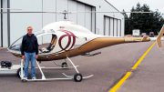
This experimental helicopter had a five blade rotor head and tested with different Subaru engines including the 3.0 L flat six, the turbo and 2.5 L normally aspirated power plants. The second helicopter built, the pre-production prototype AK1-3 Sanka, flew in July 2003. This is the helicopter I flew in during my visit in June 2005.
The factory currently covers an area of over 1200 m² with additional existing old hangars still being renovated which will then be the main assembly area. 65% of the components are manufactured in house. Pilot production started in 2005 with five helicopters being built. It was one of these, a dark green craft, that I flew on my second visit in November 2005.
Production capacity for 2006 is to be increased to ten helicopters and to 15 + for 2007. Aerokopter is a young small company co-financed by two main shareholders who are also joint share holders in a gas-oil pipeline laying business.
Depending on sales, production capacity will be increased over time to cope with future build up of orders. The factory quote a normal production lead time, i.e. time to manufacture the components and assembly, of 11 months. This of course is a little academic as actual delivery lead time will vary depending on factory workload.
As at December 2005 the ten helicopters for end 2006 delivery were all taken up and the current lead time is now end 2007. I did however notice that several new machining centers were being installed during my last visit, so capacity is already being ramped up. It’s going to be needed!
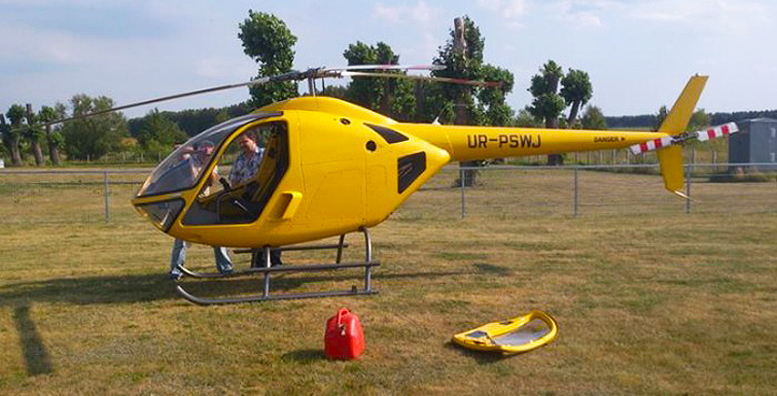
During transporting, the main rotor blades must be stored in a purpose made holder for protection. With the 1-3 Sanka running on unleaded petrol, which is available almost everywhere and also substantially cheaper than Avgas, this makes for a very convenient and mobile flying platform.
Perfect for Game capture, crop-spraying and aerial photo operations, or just taking it away on holiday with you. An incredible ability and freedom that I enjoy with my current CH-7 Kompress helicopter.
The AK1 Aerocopter Helicopter
After some market research Aerokopter concluded that a need for a light two-seat helicopter in the 650 – 700 kg gross weight category existed. The end result of the design-team’s creation is a helicopter capable of delivering a maximum vertical thrust of 800kg from its 165 HP motor at sea level. There are “flight performance graphs” available on the home page for those who wish to analyse the helicopters performance in more detail.
Airframe
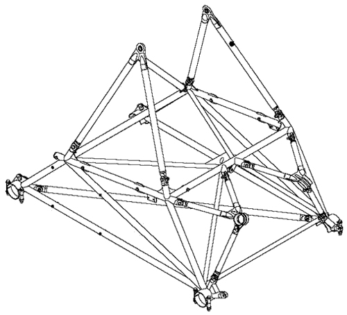
The small truss-type airframe is made of triangulated Chrome Alloy tubing with two separate upside-down “V” side frames used to attach the Main Rotor Gearbox (MRG) to the air frame. Also detachable are two engine mounting sub-frames that carry the engine weight via rubber insulated engine mounts below the engine.
On each lower corner of the airframe is welded a large circular clamp through which the 60mm diameter Titanium-tube skid legs pass through. At the front of the airframe are four attachment points that hold the cabin-structure in place.
Detachable side frames attach to main rotor gearbox.
The cabin floor is fastened on top of a triangulated Duralumin sub-frame and this sub-frame is attached to the Chrome Alloy airframe.
These skid-legs are single-piece U-bent tubes and are secured via rubber bushes inside these circular clamps.
The lower end of each Titanium skid tube has a steel foot attachment to which is fixed the Duralumin (aluminum) skids.
This titanium tube “under carriage” looks very robust yet is extremely light-weight.
Each landing skid has a machined Duralumin Dolly-wheel attachment-point and on each side of the front legs are beautifully machined Duralumin (aluminum) foot pegs to assist entry into the cabin – a minor cosmetic addition with major practical purpose.
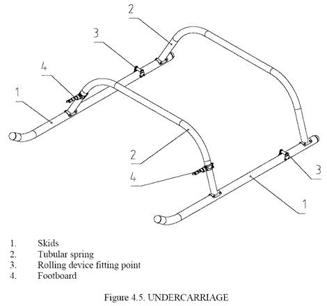
Note that the skid legs (2) are made of one single Titanium tube 51 mm diameter.
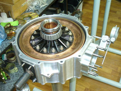
The MRG and integral primary reduction drive unit together form an upside-down “L” with a cross brace linking the two ends to form a triangle.
This triangle then forms part of the helicopter airframe structure and is the attachment point for the front of the tailboom and front Subaru engine mount.
There are two Duralumin diagonal struts that then join the lower rear corners of the airframe with the underside of the helicopter tailboom approximately two thirds down its length.
The use of the MRG drive system as part of the airframe is unusual in a helicopter and is the same principal used in formulae-one cars and super-bikes where the engine-gearbox forms part of the chassis.
By using this integrated truss-frame design has allowed the use minimal amount of aircraft chromoly steel tubing without sacrificing rigidity, but saving weight.

Basic helicopter airframe assembled and mounted on landing skids.
The tailboom is made up of four rolled aluminium sheet sections riveted together. At each of these joins there is a CNC machined ribs that supports the three tail rotor drive shaft bearings.
The entire tailboom is assembled in a jig with re-enforcing gusseting added where required and as can be seen from photos the workmanship is excellent.
Power Transmission System
Engine power is transmitted via a rubber flex-coupling to the primary reduction drive unit’s bottom poly-V-belt pulley. The reduction drive unit is made up of two machined Duralumin side frame plates separated and bolted to a central rib spacer. Between the side frames are the small bottom and larger top drive pulleys.
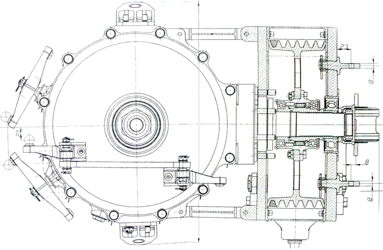
Aerokopter kit helicopter right angle main rotor gearbox.
There are two large sealed bearings supporting the bottom pulley’s steel shaft. Each reduction drive bearing sit in Titanium bearing holder which in turn is bolted to each side frame.
The upper pulley has the sprag-clutch (free-wheeling unit) incorporated into it. The steel sprag-clutch inner race is hollow with internal splines and is supported by a large sealed bearing in its Titanium sleeve at the rear.
Well machined Aerokopter helicopter gearbox.
The MRG with its splined pinion gear shaft protruding rearward then slides into the hollow sprag-clutch splines to form one integral unit.
The 40mm diameter steel pinion gear shaft is supported by two large tapered roller bearings, lubricated from MRG oil.
These two tapered roller bearings fit into a Titanium housing and this housing is in turn bolted to the MRG housing.
The three sealed bearings in the reduction drive unit each have a tela-temp to check bearing condition during pre-flight.
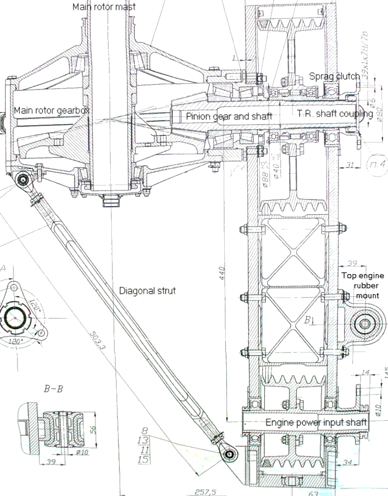
The poly-V-pulleys drive six Kevlar reinforced V-belts and the top end of the reduction drive unit is covered with a carbon-fiber shroud to keep the rain water off and so prevent possible belt slippage.
Aerokopter helicopter transmission cross section.
The six V-belts are used as the clutch on start up and are tensioned using an electric actuator operated from a switch inside the cabin. The V-belt tensioning is via a rocker arm and idler pulley assembly pushing the v-belts towards the center. Tensioning the V-belts in this manner increases the “wrap angle” around the drive pulleys thus ensuring no slippage with less belt tension.
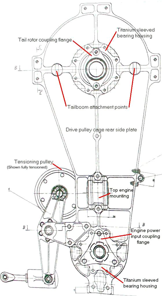
Aerokopter helicopter drive pulley cage with belt tensioner.
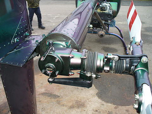
At the rear end of the top pulley shaft is a flex-plate coupling that connects to the front of the 38 mm diameter duralumin tube tail rotor drive shaft. The drive shaft is supported by three sealed bearings along its length, with another flex-plate coupling connecting to the tail rotor gearbox at rear.
The tail rotor gearbox (TRG) is constructed from a machined Duralumin casing and two Titanium housings attached at 90° housing the bearings. There is a hardened and ground spiral-bevel gear set with a large oil sight-glass at rear. There is no chip detector, but a tela-temp is fitted.
The 1-3 Sanka is designed for use in two configurations, namely as a two person craft, where the maximum gross weight is 650 kg due to center-of-gravity limitations and also as a crop-spraying craft. The MRG is designed to operate continuously at the engines maximum output of 165 HP and at an all up weight of 740kg for the crop-spraying configuration. (The crop-spraying system, still under trials, will only be available later.)
The large MRG casing is machined from solid billet and has a protrusion machined on the side to house the pinion gear assembly within its Titanium housing. The CNC machined and internally ribbed top casing houses the larger taper-roller thrust bearing, whilst the bottom externally ribbed casing supports the smaller taper-roller bearing that holds the main rotor shaft. The large 280 mm diameter spiral-beveled ring-gear and matching pinion-gear are both hardened and ground.
Aerokopter helicopter engine bay with Subaru 165HP EJ25 boxer.
A steel ribbed center section bolts to the inside of the ring-gear and is fastened to the main rotor shaft on a 64 mm diameter splined section to transfer the torque.
A section of the main rotor mast protrudes 78 mm in diameter, this above where the ring gear is attached, and this section is what carries the helicopter weight via the large thrust bearing in flight.
All the parts I examined looked more than capable of handling several times more than the mere 740 kg gross weight of the aircraft.
The MRG has no chip detector, but has a magnetic plug, a large oil sight-glass and a temperature sensor. I can say that the gearbox’s both run cool, as after a 30 minute hovering session in the factory yard with two on board I could comfortably hold my hand on the MRG (approximately 50 – 60°C) and the TRG was only luke-warm. It was however a cold day with outside air temperature at 4°C.
Rotor System
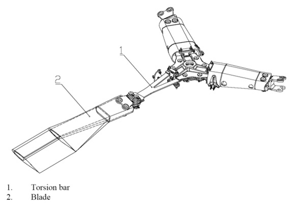
Aerokopter rotorblade assembly.
The rotor head design used on the 1-3 Sanka is unusual and unique for such a light helicopter.
The technical name is a “Laminated Blade Retention System” also sometimes called a laminated torsion bar system.
This system is currently used on both the American Apache-Longbow and the Russian Black-Shark attack helicopters.
It is also used on some Mc Donald Douglas helicopter models. The main rotor has three composite blades rotating clock-wise, whilst the tail rotor has two composite blades.
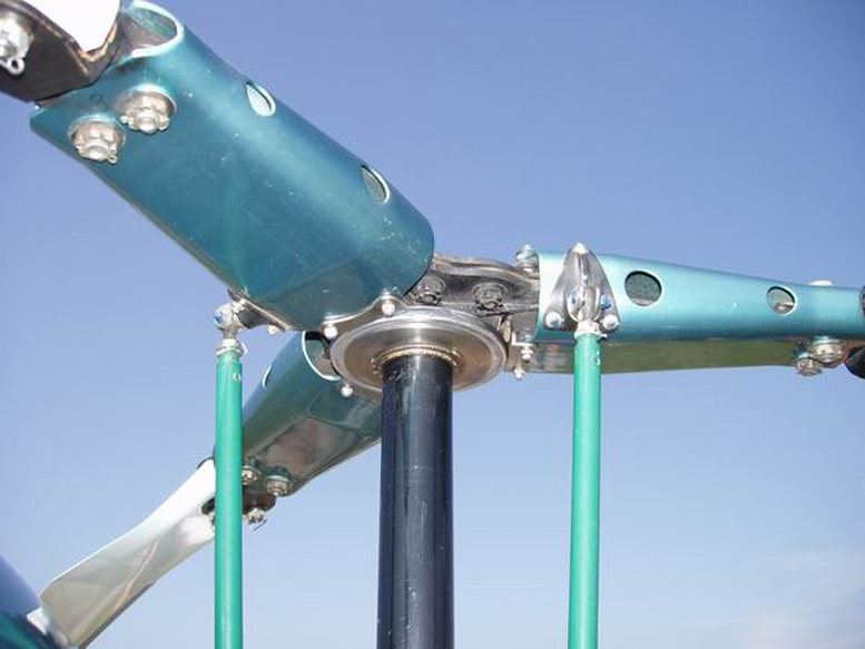
Aerokopter helicopter military grade main rotor system.
The Laminated torsion bars (LamTB) are each made from a stack of 17 thin Y – shaped VNS-2 steel plates totaling approximately 5.5 mm thick.
Each separate plate is coated with a permanent lubricant coating on one side and the tested tensile breaking point per plate is 1,330 kg, thus giving a safety factor of greater than three times the 7,000 kg centrifugal blade tension at full rotor rpm.
These torsion bars are very flexible up and down, can also twist easily and replace the more conventional, but bulky and heavy lead-lag, flapping and feathering hinges commonly used. The best comparison I can think of is a stack of engine feeler gauges that also bend and twist easily.

Helicopter main rotor torsion bar blade strap with pitch-link torque-tube cover.

Aerokopter helicopter torsion bar destructive test.
- Feathering torque tube (composite)
- Duralumin pitch link ear
- Outer hub assembly
- Titanium torque tube inserts
- Pitch link fork
- Laminated VNS-2 metal torsion bar
- Rotor blade grip (steel)
- Feathering center point body
- Blade grip & torsion bar bolts
- Fastening plate
- Blade grip & torsion bar bushes
- Blade droop-stop plate
- Plate spacers
The rotor hub consists of two steel components. The top element has a central hollow boss which is splined and fixed to matching splines near the top of the main rotor mast.
The lower section is the same outline shape as the top, but with a clearance hole in the centre where the mast passes through.
These two elements together with their six large bolts form a clamping devise. The LamTB’s are bolted and sandwiched between these steel rotor head elements on the inside and to the steel blade grips on the outside.
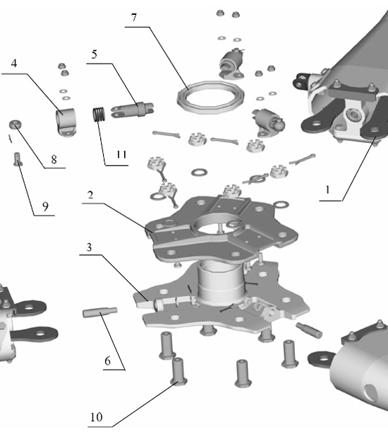
AK-1 helicopter main rotor hub.
In this rotor hub assembly image the droop-stop is mechanism shown upside down below for clarity.
For rotor blade pitch control, a composite torque-tube is placed over the LamTB’s, fixed to the steel blade grip on the one side and, has a central pivoting bearing on the rotor hub side to allow for blade feathering.
On the outside section of the torque tube nearest the hub is a machined Duralumin “ear” that the pitch-links connect to.
There are four large inspection holes at the front and back of each torque tube to allow easy inspection of the LamTB’s during pre-flights.
The move away from two bladed teetering rotorblade system in the Aerokopter helicopter offers a margin of safety eliminating negative “G” situations that usually result in mast bumping and tail boom separation when the blade strikes the tail.

- Torsion bar
- Bottom rotor hub plate
- Top rotor hub plate
- Droop-stop bush
- Droop-stop pin
- Torque-tube feathering pin
- Droop-stop ring
- Droop-stop pin roller
- Droop-stop roller pin
- Rotor hub & torsion bar clamping bolts
- Droop-stop pin spring
The tail rotor system also uses a straight laminated torsion bar instead of thrust bearings to contain centrifugal forces as explained in ther next section.
The Tail Rotor Hub

Aerokopter helicopter tail rotor hub assembly.
- Body
- Socket
- Fork
- Hub
- Fork nut
- Damper
- Laminated metal torsion bar
- Torsion bar bushes
- Fork washer
- 11. 12. Fork bearings, bushes, nut & washers
The major advantages are mechanical simplicity, massive weight savings, ease of inspection and no service maintenance. The main rotor head torsion bars are non-serviceable items and must be replaced every 500 hours of flight time. (Not 2000 hours as I had incorrectly stated in my article of June 2005)
As more field experience is gained this replacement time may be extended in the future. The replacement of these torsion bars does not appear very difficult to perform. The tail rotor torsion bar is replaced at 2000 hours.
AK-1 Aerokopter helicopter tail rotor gearbox.
The composite main rotor blades have a non-linear -9.5° twist and a variable profile NACA 63012 / 63015.
They are constructed by first creating a “flattened D” shaped spar from Kevlar composites with 2 kg of lead weight imbedded in the outboard 2 meters of the front leading edge. This spar is then cured in its electrically heated mould.
This high tensile “D” spar is then placed into the blade mould together with Rohacell foam trailing edge inserts. This whole assembly is then skinned in Kevlar and cured.
Titanium bushes are placed at attachment points and the leading edge wear strip is applied once the blades have been cleaned and painted. Each finished blade weighs 7.7 kg and there is no time life on these blades.
The tail rotor blades are also made of Kevlar and Rohacell foam with a leading edge wear strip. Both the main and tail rotor blades have no time life and are only replaced on condition.
The outside appearance and quality of the rotor blades was excellent. I noticed that none of the helicopters I had flown in had trim-tab blade adjustments, yet both were smooth in flight.
Flight controls

Aerokopter helicopter cyclic and collective controls mounted under the cabin floor.
The 1-3 Sanka has standard helicopter dual controls with cyclic and collective stick controls having adjustable frictions. The cyclic friction is on the left stick ( Solo-seat position) and uses a floor mounted dome friction system with a rotating collar around the base of the stick for adjustment.
The collective friction is at the base of the central collective stick and is adjusted by means of a horizontal wheel. I did not notice a throttle friction, but in flight the throttle stayed pretty much where you left it, so there did not appear to be a need for one.
The collective stick movement is correlated with the throttle and does a good job of keeping engine and rotor rpm in the “green band” for normal moderate flight conditions with only small pilot input required during transitions.
A throttle governor system is offered as a factory fitted option to make pilot control even easier. This governor system consists of a Subaru “cruise-control” unit adapted for helicopter use.
It is switched on and off with a push-button on the cyclic grip. There is also a coolie-hat switch at the top of the cyclic grip that allows you to toggle the governor speed up or down for cruise flight or for take off and landing. On the cyclic grip, there are three other push buttons, one for the radio, one for engine start and one spare. (Maybe to operate an ejector seat!)
The anti-torque foot pedals are not adjustable, but if it was really needed for say a very short person, it would not be too difficult to make an adjustable system. I did find all the controls comfortable, easy to reach and operate, and for my height of 1.81 meters, were all well placed.
The collective and cyclic control inputs are transmitted to the rotor system via Duralumin tube control rods and levers. The anti-torque control inputs are transmitted via a combination of levers, cables and pushrods. All moving parts of the control system rotate in sealed bearings and all fasteners are either safety-wired or use castle-nuts with split-pins for security.

Helicopter flight controls and swash plate.
The collective lever has an unusual “neutral-stick” feature fitted just below the cabin floor. The purpose of this feature is to hold the collective down when not in use and once lifted up, as in flying, it becomes neutral in weight and stays pretty much in place with minimal collective friction applied.
This prevents pilot left arm fatigue on longer flights, but still allows one to lower the collective in an emergency. It achieves this mechanically via a spring loaded override mechanism. The detail mechanical workings of the control system below the cabin floor, can be studied from attached photos of an unpainted factory mock-up.
Three long control-rods, for cyclic and collective control, route vertically aft of the cabin and connect to three small walking-beams attached to the front of the MRG. From the opposite side of each walking-beam is a short control rod that links to the static lower swash plate spider. Then from the top rotating swash plate spider are connected the three blade pitch control rods.
The swash plate has rubber bellow covers top and bottom protecting the fiber ball and rotor mast from dust and water where they slide against each other.
Anti-torque control inputs are transmitted from the foot pedals via levers to a semicircular cable pulley below the cabin floor. Attached to this semicircular pulley are two plastic sheathed stainless steel control cables going aft and guided by numerous grooved rollers to another identical semicircular cable attachment pulley at the rear of the tailboom. From this rear semicircular cable pulley is a short control rod connected to the tail rotor pitch control lever.
The tail rotor pitch slider also has two rubber bellow dust covers to keep water and grime out. All the grooved cable guide rollers have ball bearings and a safety bar/tab across the top of the groove above the control cable, thus preventing the possibility of a slack cable jumping out from the guide rollers.
My general impression of all the control components are that they are well machined, robust and should comfortably last the 2000 hour life of the helicopter before overhaul.
Cabin

Helicopter composite cabin floor.
The composite cabin floor together with its lower triangulated aluminium sub-frame are the main structural elements. The floor is made of a 16mm plywood with machined out different sized squares so as to leave a light wooden grid. This wooden grid matches with all the required attachment points for the sub-frame and other control attachment points. All the machined out wooden spaces are then filled with machined foam inserts to replace the wood removed.
Then a skin of Carbon-Kevlar cloth is applied to both sides resulting in a very light and rigged structure. The lower Duralumin frame is made up of riveted together CNC machined elements which are attached to the rest of the airframe.
The two seat frames are made from Titanium tubing, drilled aluminium sheeting for the cushion base and covered with sponge and fabric. Each seat is equipped with a 4-point safety harness, the shoulder harness being anchored to the floor/sub-frame at rear of each seat.
The rounded shaped cabin upper body is made from Carbon / Kevlar cloth with the four separate tinted polycarbonate windscreens bonded into place, thus forming one single light rigged structure.
Aerokopter helicopter all composite cabin.
The lower belly-panel, also made from Carbon / Kevlar cloth is held in place with screws just below the floor, thus allowing access to control linkages and electrical wiring loom if needed.
The Carbon/Kevlar door frames are bonded to the tinted polycarbonate windows and a rubber extrusion fitted around its inner edge. Each door is fixed with two hinges up front and closed with a simple latch at the rear. By removing the two hinge pins, each door can be easily removed if required. The VNE is limited to 170 km/h with doors off at sea level.
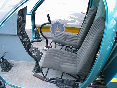
The instrument pedestal is constructed of riveted aluminium sheeting and the three separate front panels cascade down at varying angles to better match the pilots view. The pedestal also houses the cabin heating system with its plumbed hot water from the engine, small radiator and electric fan and its temp controls. For S.A. with our hot climate, this cabin heating system and its associated plumbing will not be installed, thus saving approximately 7 kg in weight.
The top panel houses the flying instruments and 9 warning lights. Standard instruments include, Altimeter (In feet with milibar subscale for SA), Artificial horizon, Airspeed indicator (In Metric Knots for South Africa), vertical speed indicator (In feet/min for SA), an engine manifold pressure gauge for SA, Rotor and engine rpm indicator, Blade pitch indicator and slip-ball indicator.

The center panel houses fuel gauge, engine oil and water temperature gauges, the Microair airband VHF radio/com, the master, ignition and clutch switches for the Subaru engine and the cabin heat controls. – The bottom instrument panel houses six (6) switches and the electrical fuses. – The Hobbs hour meter is fitted on the left side of the pedestal.
If there is one element of the 1-3 Sanka I had to criticise, it would be for its panel layout. It is an OK/average panel layout, but compared to the outstanding quality of the rest of the aircraft it is mediocre by comparison. The panel layout is being reviewed for S.A. and when finalized more information will posted.
Overall the cabin is very spacious and comfortable for two persons and at 1.353 mm wide you don’t rub elbows. By comparison the Robinson and Rotorway cabins are 1.100 mm wide. There were two hooks for hanging of headsets in the top center of the roof and the rear cabin bulkhead was covered in a felt like material.
The quality of fit and finish was high and other than the panel layout review, I would only add two small rubber mats where the heel of your shoes would soon spoil the carpeting. ….Mere nitpicking details!
An option that can be ordered separately, is the lighting package. This consists of three navigation lights, a strobe, a landing light, a cabin light and two panel lights. Unusually, the aft navigation light is located at the end of the tail fin “skid” tube.
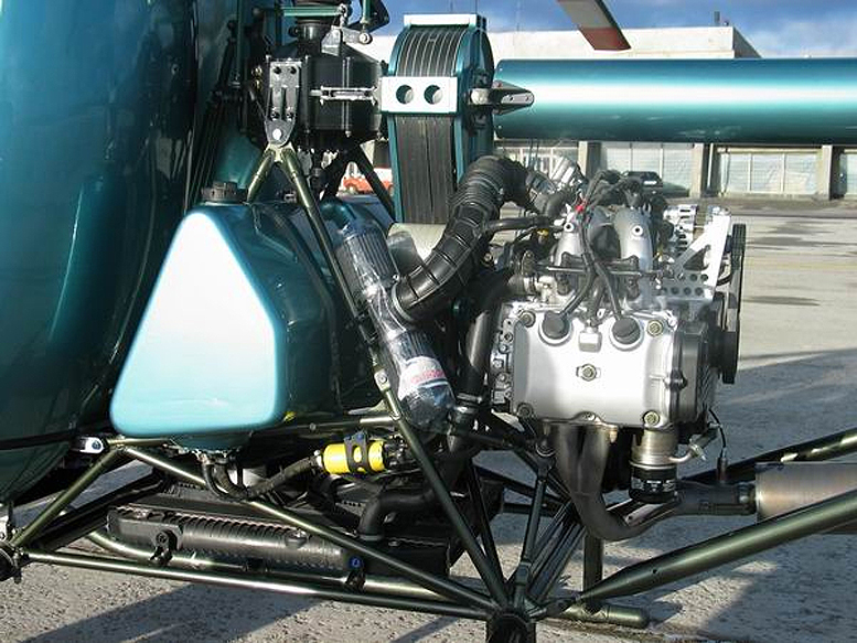
Subaru Engine
The 1-3 Sanka is powered by the proven and extremely reliable Subaru EJ 25 motorcar engine developing 121 kw. (165 hp)
This engine is a modern, water cooled flat four cylinder, (Boxer) with fuel injection, single overhead camshaft, four valves per cylinder, hydraulic-tappets and solid state electronic ignition and duel fuel pumps.

The Subaru EJ25 boxer engine power-torque graph.
The engine’s bore to stroke dimensions are over-square at 99.5 mm by 81 mm.
This over-square characteristic typically allows engines to operate at higher rpm more easily without overstressing, and also enables the use of larger inlet and exhaust valves, thus allowing easier engine breathing at higher rpm.
The engine is very smooth indeed at all engine speeds. The engine automatically adjusts the fuel mixture for varying altitudes, so there is no mixture adjustment required by the pilot.
In the 1-3 Sanka with the rotors turning at 572 rpm (105.5% – top of green band) the engine turns at 5,600 rpm, so as to have full power available when lifting off or landing. Bottom of green band equals 5,000 rpm and level flight cruise with governor set to middle of green (100%) equates to 5,300 rpm.
In the early years of flight, big bore slower turning motors were developed for propeller aircraft to avoid having a reduction gearbox between it and the propeller. (The tips of the propeller are not to exceed the speed of sound, and they had problems building light weight reliable gearbox’s back then) Also, electronics (read magneto ignition systems), were not too reliable then and it was prudent to have a back up…i.e. with twin magnetos.
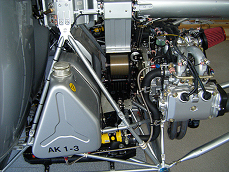
Aerokopter Subaru EJ25 helicopter engine and central mounted fuel tank.
This in essence is the crop of traditional certified aircraft engines still manufactured and available today and they still all run on high lead Avgas fuel developed during the 2nd World War.
These engines tend to be costly due to low volume production and with frequent technological advancements to the design impeded due to the crippling costs of re-certification each time and the very high cost of engine research that has to be recouped over such low volumes.
But this is 2006 not 1946 and we have moved on somewhat with motorcar and motorcycle engine technology surpassing the traditional aircraft engine by leaps and bounds in terms of performance per displacement and excellent high production volume cost efficiencies, reducing purchase and operating costs, whilst continually improving reliability.
For helicopters the operating speed of the motor is irrelevant, as it must be geared down to turn the relatively slow turning main rotors, so higher spinning motors are no problem. Some small helicopter turbine engines spin at 40,000 rpm so high speed petrol engines are slow by comparison.

Aerokopter helicopter factory standard Subaru EJ25 engine.
Some folks will baulk at the idea of a single ignition system on an aircraft engine as magnetos do some times fail, but cars moved away from magneto ignition (50 to 60 years ago?) in favour of points and distributor, then finally to present day electronic ignition with no moving parts to wear out, improving reliability (In all weather conditions) and lowering costs.
Each spark plug on the Subaru has its own ignition coil and the entire electronic ignition system is totally waterproof. I flew twice in rain (With engine electronics total exposed to water) and their test pilots had flown several hundred hours including in rain and snow without missing a beat.
I did a little research myself by speaking to the two senior Subaru mechanics and asked them how often they had encountered an ignition failure or a catastrophic mechanical failure on any model Subaru car in the six years that the Bellville/Cape Town workshop has been opened? ….Not one.

Subaru helicopter engine and main rotor drive belts.
These engines are in cars driven every day by ordinary folks, summer and winter. When last did you experience ignition failure in a car of 1995 vintage onwards, or know of some one else who has experienced this problem? Don’t confuse car alarm systems shutting the car off, …the Sanka does not have a burglar alarm!
I am no agent for Subaru, although I did discover it and purchased a 2.5 Subaru Forrester 18 months before I knew that the 1-3 Sanka existed, but to those who have never driven in a Forrester, ….be brave, forget status and test drive one to experience the motor! (The car by the way is also very nice to drive!)
All modern car engine designs undergo a 500 hour test at full throttle (100% power) after which the engine is dismantled and inspected. After such a test there should be minimal wear to any of the engine components. (Technical questions – Car magazine November 2005)
Besides being an excellent engine (Subaru is the most popular motorcar engine used in experimental / amateur built / kit aircraft world wide) it is inexpensive to service or overhaul, as one is charged “car” instead of “aircraft” prices.

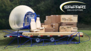
The very capable Subaru powered Aerokopter fitted with crop dusting equipment (see blue drum and spray arm).
Another financial advantage is the substantially lower cost of petrol compared to Avgas ( Approx. 30% cheaper) plus the big convenience of having it available every where and the fact that it pollutes less. I have found that operating only from the larger airports, where Avgas is usually only available, somewhat diminishes the flexibility and go anywhere advantage of a helicopter. Off course one can organise a ground crew to road haul drums of fuel to where you want to fly to, but what a schlep! You may as well ride in the truck!
On the 1-3 Sanka Subaru engine, the standard inlet manifold has been rotated 180° so that the air filter faces rearwards. The 70 amp alternator mounting bracket is specially made so as to move the alternator off-center and likewise the exhaust system is manufactured by Aerokopter without the catalytic converter. The positioning of the exposed engine on the Sanka makes it the easiest engine to service of any helicopter.
For more information please visit: Aerokopter Southern Africa

I like aviation and looking forward to be receiving updates on ak1-3 helicopter
Not too sure whats happening with the AK1 helicopter at the moment. It was originally designed and built in the Ukraine.
“The Aerokopter AK1-3 is a Ukrainian helicopter, designed and produced by Aerokopter (also spelled “Aerocopter”) of Kharkiv.”
https://en.wikipedia.org/wiki/Aerokopter_AK1-3_Sanka
The Russian invasion of Ukraine would be having an effect.
Somewhere along the line, Russia copied the design and sold it as there own as both a 2 seat helicopter and drone.
Pozdrav. Mogu li dobiti kontakt od firme koja proizvodi ovaj helikopter