

I know that most of you have seen flutter happening. A great example is the tie-down straps on your trailer. They look good until you’re driving down the road. There in your rear-view mirror there’s the image of the straps just fluttering like mad.
Ok, you stop and tighten them down. Again driving at speed you see the straps still fluttering. If you’re observant you noticed the flutter frequency increased as the straps were tightened. With experience you’ve found that it is necessary to run the straps with a twist to eliminate strap flutter.
Putting that twist in the strap upsets the aerodynamics and usually only one twist is required to stop the flutter. Now, take a look at your rotor blade. It, like your tie-down strap, is longer than it is wide or thick and is usually metal or a combination of metal and composite.
The tie-down strap is usually nylon. Both strap and blade have characteristics that embody spring like behavior. However, your blades are stiffer than the straps. This causes them to have higher flutter frequency both in twist and flap.
Of course the higher the rotor rpm the stiffer and the higher the flutter frequency. Hopefully this flutter frequency it is out of range of any resonant frequencies of any other element of your ship.
That is, we don’t want some other part shaking at a frequency that will excite a flutter in the blade. Now to draw on the information gained by some folks who have made a much deeper study of the flutter phenomena. First a quick look at some different classes of airfoils.
Symmetrical Airfoil

It is easy to see that the airfoil is symmetrical about the chord line or the line connecting the furthest most tips. This airfoil has been used for a long time on helicopter rotor blades and for some competitive aerobatic aircraft.
Properly designed and constructed, there is a stabilizing effect on the rotor blades and an equal lift force, whether right-side up or up-side down, for the aerobatic aircraft. The stabilizing effect of the symmetrical will be discussed in more detail later.
Cambered Airfoil

The cambered airfoil is what is typically seen on the everyday fixed wing aircraft. It generates good lift and often benign stall characteristics.
Reflex Cambered Airfoil

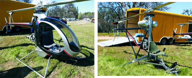
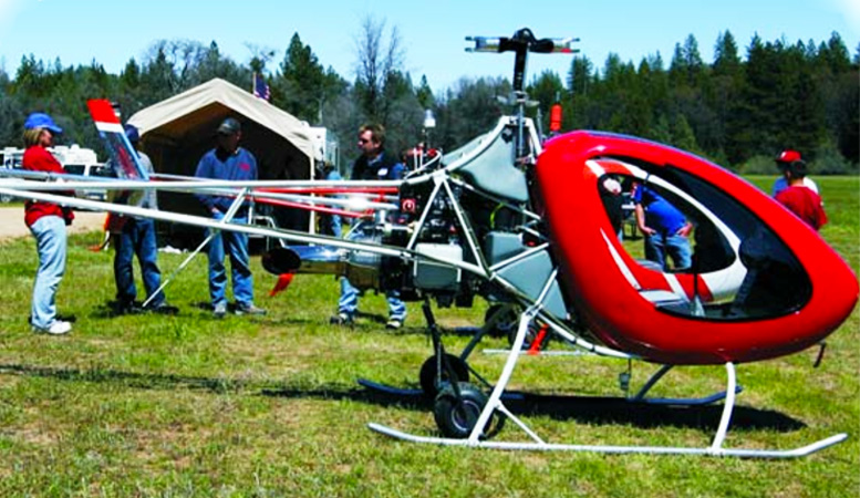
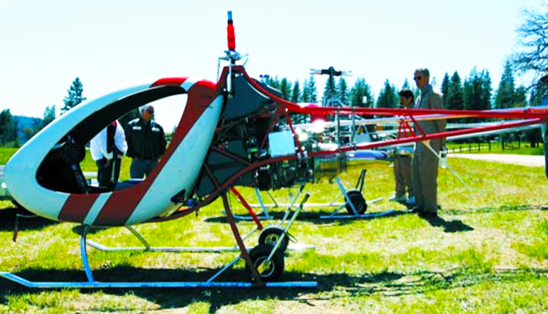
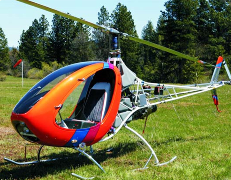
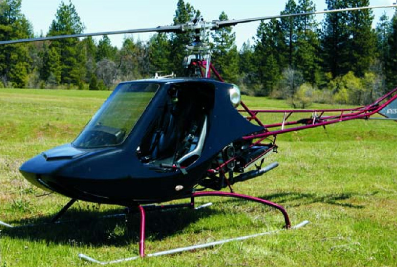
This reflex cambered airfoil is being used on a lot of modern helicopters and in particular the Helicycle helicopter. The use on the Helicycle is the main reason for this article.
Center of Pressure
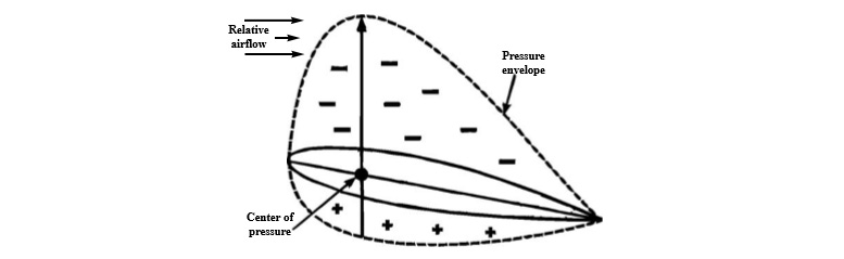
Position of center of pressure determined by the shape and size of the negative pressure envelope above and the positive pressure envelope below the airfoil. For a given symmetrical airfoil, center of pressure position is essentially fixed with changes in angle of attack. Taken from “Principles of Helicopter Flight, Wagendonk, ASA-PHF, 1996, pg 21
Before examining some of the aerodynamics of the various airfoils, let’s start out with a discussion of what has been called the Center of Pressure. If you have an airfoil in a wind tunnel and can measure the pressure at the surface of the air foil, you will find that it varies from the leading edge to the trailing edge.
(See the sketch below describing pressure measurements as distributed about the airfoil chord.)
It is possible to replace the pressure envelope with an equivalent single force located at the “Center of Pressure”, as illustrated in the graphic below.
Prouty says, (If you are interested in helicopters you will know who Prouty is) that “For all shapes with a sharp trailing edge, theory and experiment place the center of pressure near the quarter-chord.” e.g. for a blade that has an eight inch wide chord, the 1/4 chord is two inches aft of the leading edge.
In the symmetrical airfoil, the center of pressure and the chord wise c.g. of the blade were used in the blade design to compute expected pitch moments. These pitch moments coupled with the flapping stiffness of the blade helps in forecasting blade flutter characteristics.
Note: The chord-wise c. g. is the point located aft of the leading edge where the blade would balance on a pointed rod, supporting the blade at that point. If the point is also at the spanwise c. g. then the entire blade would balance at that point, on the tip of that pointed rod.
Of course your tie-down strap is in fact a symmetrical airfoil with a c. g. at the 1/2 chord. Keep this in mind for a discussion that is taken up a bit later.
Symmetrical Airfoil
For a symmetrical blade, with the chord wise c. g. located on the quarter-chord, and since the center of pressure is co-located and doesn’t move as a function of the angle of attack, essentially zero aerodynamic pitching moments are generated on the blade for all angles of attack of the blade short of stall.
The result is a normally stable blade as far as flutter is concerned. The center of pressure has long been used as the center of lift or the single lifting force that is the equivalent of the lift being generated by the wing. The symmetrical airfoil at zero degree angle of attack would generate zero lift.
The pressure profiles are identical both above and below the airfoil. Their resulting center of pressure, both above and below, occurs at the 1/4 chord point and zero pitching moment is generated.
Cambered Airfoil
It is easy to see that this airfoil is not symmetrical about the chord line but has a significant cambered shape above when compared with the camber below. The Cambered airfoils behaved aerodynamically differently from their symmetrical cousins.
These forms produce a nose down pitching moment, even for the zero angle of attack. Assumptions were made that the moment was produced by lift acting on a moment arm extending aft from the normally used quarter-chord point.
With this assumption calculations could be made to find a “Center of Pressure”. This of course didn’t explain the nose down pitching moment in the presence of zero lift, and is therefore a problem that Prouty said, “led to the conclusion that cambered airfoils are unstable”.
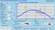
According to him, this conclusion is still existent in current readings like Chapter 2 of the newly-issued FAA Rotorcraft Flying Handbook (2011). Prouty recommends a better visual model of recognizing that the “Aerodynamic Center” is defined as the point for which the pitching moment is constant for all angles of attack, up to and not including, blade stall
He further reports that tests on both symmetrical and cambered airfoils show this point to be very close to the 1/4 chord. This is illustrated by Prouty in the chart at the top of the following column.
It seems that just this relatively small change in view point may have helped open the door for helicopter blade designers to look again at the cambered airfoils. In the past the nose pitching down moment created some real havoc in rotary wing aircraft.
There were stories that some autogiro pilots encountered the phenomena and were unable to recover control of the blades. Other actual reports, from pre-maturely grey haired pilots, having encountered this instability and lived to tell about it, scared designers away from the airfoil in spite of stronger lifting characteristics.
Well, it makes sense — if it doesn’t work, don’t use it. The last airfoil of interest here is Reflex Cambered Airfoil. This airfoil adds a trailing edge that is deflected up from the normal chord line of the plain cambered airfoil.
With just a little imagination you can see that the air flowing over the airfoil, and hitting the reflexed trailing edge, would tend to cause a nose up pitching moment tending to offset the normal nose down moment of the plain cambered airfoil.
The little addition gave blade designers a device to allow them to expand their designs into airfoils that generated more lift and other characteristics useful for specific helicopter mission designs. OK, all that is interesting but how does it affect flutter?
Bramwell, in his excellent book entitled “Bramwell’s Helicopter Dynamics”, states on page 324, that for the flutter type of instability to occur, a mechanism which couples blade pitch and flap is required. He further states that the normal type of coupling encountered is caused by adverse offsets of the chord wise center of gravity (CWCG) of the blade section.
Wayne Johnson, on page 638 of his book, “Helicopter Theory”, states that “Centrifugal forces couple the flap and pitch motion if the center of gravity is offset from the feathering axis.” The normal method used to insure that the CWCG is on, or forward of, the 1/4 chord point is the use of a mass located in the leading edge of the air foil.
Brass rods, lead rods, etc have been used to beneficial effect. Evidently the “Center of Pressure” for the tie-down strap occurs near the 1/4 chord while the c. g. is located at the 1/2 chord. The strap manufacturers don’t warn you about this aerodynamically unstable condition of their offerings….Tsk.
However, there are more physics of the air foil shapes themselves that produce interesting effects. For symmetrical airfoils the center of pressure is said to lie close to the 1/4 point, measured aft of the leading edge.
According to J. Gordon Leishman’s, “Principles of Helicopter Aerodynamics”, as the angle of attack and coefficient of lift increase, the center of pressure does not move. As a result, the collective pressure shouldn’t change.
Assuming that the center of gravity lies ahead of the center of pressure, positive longitudinal stability should occur. This has been the air foil of choice for helicopter blade designers for years. Though it lacks some positive characteristics found in the cambered air foils, it does have a more positive stability and is easier to fabricate.
However, if the center of gravity lies behind the center of pressure, a moment is generated creating a pitch-up tendency of the blade only to be resisted by the springy elasticity of the blade and the stiffness of the collective and cyclic controls.
A sudden increase in the effective forward velocity will, through the increasing upward flap, further try to increase the angle of attack flap-pitch-coupling created by the trailing edge heavy condition as referred to in Bramwell.
This does not lead toward stability. Since the center of pressure and the resulting aerodynamic center tends to be stationary at a point close to the 1/4 chord point, the blade designer only has to be careful to keep the CWCG on, or ahead of, the 1/4 chord point with the pitch axis also very close to this point, to have the resulting pitching moments essentially zero.
Note: It would be interesting to sew a thin lead thread into the leading edge of a tie-down strap to move the c. g. from the 1/2 chord to the 1/4 chord position to see if the strap flutter went away.
On one helicopter that uses symmetrical blades, the blades are trailing edge heavy to the point that some 50# of spring force, connected to the collective, is required to maintain a near zero collective force in flight.
There is obviously a strong nose pitch up moment being generated in the blades. These blades fall into the category of being more prone to flutter, as described by Bramwell. There has been one instance where the collective was lowered with strong aft cyclic during a quick stop, resulting in a vibration strong enough to bend the tail boom.
Another ship, when the collective was lowered without sufficient reduction in throttle, experienced very high vibration, but without structural damage. Looking now at the cambered airfoils, what about them created the impression of unsuitability for helicopters?
Again using J. Gordon Leishman as a source, the center of pressure on this airfoil is not at a fixed location but varies as the angle of attack and lift coefficients vary. To wit, for the conventional cambered air foil, the center of pressure lies slightly aft of the 1/4 chord point at the maximum angle of attack.
With a reduction of both the angle of attack, and lift coefficient, the center of pressure moves toward the rear of the air foil. One result is that with zero angle of attack the air foil generates no lift but does still have a nose down pitching moment.
The net effect of the pressure distribution on the top and bottom of the airfoil, at zero angle of attack, generates no lift. However, the movement of the center of pressure aft on the airfoil does still generate the nose down pitching moment.
Note that the pressure may decrease when the center moves aft but the moment arm is increasing. Assuming the reduction of the angle of attack was commanded by the pilot, this movement of the center of pressure to the rear induces nose pitch down, which tries to continue the reduction of angle of attack so the airfoil tries to further decrease the angle of attack.
The process would try to pull your collective down more. If the original reduction in angle of attack was caused by turbulence, then the movement of the center of pressure is again going to try to continue decreasing the angle of attack.
This amounts to the positive feedback inherent in unstable servo systems. The action is destabilizing and thus is the reason helicopter designers have avoided the conventional cambered air foils.
If you notice, the conventional cambered air foils on most of the “Stuck Wing” aircraft have a horizontal stabilizer located to the rear to stabilize this pitching down tendency. Reflex Cambered Airfoil Example The Reflex Cambered airfoils have a trailing edge that is deflected up from the chord line.
In this airfoil, the center of pressure is located ahead of the 1/4 chord point and as the angle of attack and coefficient of lift decrease this center of pressure moves forward. The air foil generates a pitch up tendency as opposed to the pitch down of the conventional cambered air foils.
Thus the direction of motion of the center of pressure is said to be stabilizing, as opposed to the action created by the straight cambered air foil. If you were pushing down on the collective this would tend to push back, thus stabilizing the system.
In turbulence induced reduction of the angle of attack, the movement of the center of pressure forward would tend to offset the turbulence effect. This is equivalent to negative feed back that is found in stable servo systems.
Ray Prouty says, “On airfoils with flat, tab-like trailing edges, the aerodynamic center is 2% to 3% behind the 1/4 chord.” Further he says that, “The resultant stabilizing effect is large enough that the (leading edge) balance weight can be smaller than on blades whose airfoils have more blunt trailing edges.”
He continues, “The designer will try to have the CWCG on or ahead of the blade’s quarter chord.” If you don’t have Prouty’s Volume I & II of his “Helicopter Aerodynamics”, you are missing a great read. Prouty can explain anything without resorting to a lot of math.
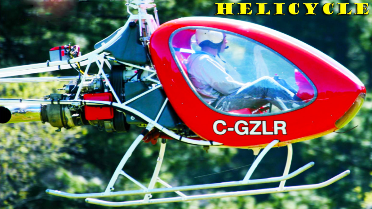
I’m jealous. Now, it has been reported that the Helicycle, which uses a Reflex Cambered Air foil, has experienced blade flutter. The above references have said that blade flutter is an unstable condition of the blade oscillating in both flap and pitch.
How come?? We just got through stating that the reflex cambered air foil has a tendency toward more longitudinal stability. Is it possible to get a reflex cambered air foil to flutter?
Evidently the answer is “Yes!!” Doug Schwochert, who does a lot of Helicycle helicopter check outs, reports that if the trailing edge of the blade is bent up too much, something like 6 degrees, flutter can be experienced in a descending flight mode.
It is possible that some owners try to adjust the collective pressure by deflecting the reflex trailing edge. This is dangerous if you don’t know exactly what you are doing. Doug also reports that with the proper adjustment of the trailing edge, he has not experienced the blade flutter.
Further he found it possible to exit the flutter, should it be encountered, by increasing collective and forward cyclic, enabling him to just fly out of the problem. This is supported by C.W Stammers, in his article titled “The Flutter of a Helicopter Rotor Blade in Forward Flight” where he stated that “forward flight has a stabilizing influence on flutter”.
Of course you still have to go thru that area of control and airspeed when you approach you landing spot.
Evidently, and I’m now guessing, the high angle of the trailing edge creates an excessive pitch-up moment on the blade, which the spring-like torsion of the blade resists, with the result of a relatively un-dampened spring-mass combination being excited by a varying force of lift and drag.
I think it would be interesting, and I will do it as soon as I have my Helicycle blades ready for flight, to locate the CWCG on both blades. If anyone has done that already please let us know what you found. There are a few relatively easy techniques for finding the location both span and chord wise – search the web for more information.
In summary, it seems possible that trailing edge heavy symmetrical blades can flutter (erosion of paint from the leading edge moves the c. g. aft). Careless application of primers inside aluminum blades can cause the c. g. to move aft. Also, reflex camber blades can flutter if the trailing edge is deflected too high.
Adjustments to the reflex angle needs to be done by someone who knows what they are doing and are aware of the dangers of too much bend. There, you now have some information about rotor blade air foils that you didn’t know but flew anyway.
Sitting around in the bar you can easily snow your buddies by constructing an argument based on your knowledge of airfoil flutter. Probably the best thing this article contains is references to some of the outstanding works on helicopter aerodynamics.
It is well worth repeating to all helicopter operators, get the “Helicopter Aerodynamics” books, volumes I and II by R. W. Prouty. If you are a helicopter designer, get the books by Bramwell, Johnson, Leishman and others.
While the math can get heavy in these books, it is better to have your designs at least contained by theory rather than have your pilots become beta testers for a seat-of-the pants design. Remember NHFY, which in this case refers to None Have Fluttered Yet, is not a sufficient statement of design quality.
References
Helicopter Aerodynamics, Vol. I, R. W. Prouty, HeloBooks div of Mojave Books LLC (http://www.amazon.com) Helicopter Aerodynamics, Vol. II, R. W. Prouty, Eagle Eye Solutions, LLC Bramwell’s Helicopter Dynamics, A.R.S Bramwell, George Done, and David Balmford, Co-published by American Institute of Aeronautics and Astronautics, Inc. and Butterworth Heinemann Principles of Helicopter Flight, W.J. Wagtendonk, Aviations Supplies and Academics, Inc Helicopter Theory, Wayne Johnson, Dover Publications, Inc. The Flutter of a Helicopter Rotor Blade in Forward Flight, C.W. Stammers, Aeronaut Quarterly, Feb 1970.
Be the first to comment on "Blade Flutter and the Various Air Foils"